


PART 2
SETUP
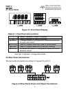
2.1 Front Panel
Figure 2.1 Front Panel Display
Table 2.1 Front Panel Annunciators
1 Output 1/Setpoint 1/ Alarm 1 indicator
2 Output 2/Setpoint 2/ Alarm 2 indicator
a
/MENU Changes display to Configuration Mode and advances
through menu items*
b
/PK/GRS Used in Program Mode and Peak or Gross Recall*
c
/TARE Used in Program Mode and to tare your reading*
d
/ENTER Accesses submenus in Configuration Mode and stores
selected values*
* See Part 3 Operation: Configuration Mode
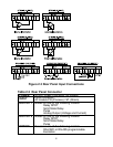
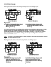
2.2 Rear Panel Connections
The rear panel connections are shown in Figures 2.2 and 2.3.
Figure 2.2 Rear Panel Power and Output Connections
1
/
8 DIN
1
/
32 DIN
1
/
16 DIN
5
8 7 6 5 4 3 2 1
6 5 4 6 5 4 6 5 4 3 2 1 3 2 1
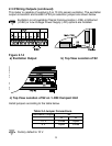
Refer to the Quick Start
Guide for assembly and
disassembly instructions.