


Nortel Secure Router 8012
Hardware Description
Issue 5.3 (6 April 2009) Nortel Networks Inc. v
Tables
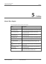
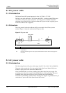
Table 5-1 Pin assignment of console cables .......................................................................................................5-3
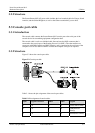
Table 5-2 Pin assignment of AUX cables ...........................................................................................................5-4
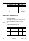
Table 5-3 Pin assignment of straight-through cable............................................................................................5-6
Table 5-4 Pin assignment of crossover cable......................................................................................................5-6
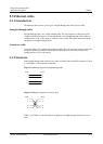
Table 5-5 Relationship between the interface type and corresponding optical fiber ..........................................5-7
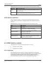
Table 5-6 Pin assignment of 4E1/4CE1 coaxial cable ......................................................................................5-10
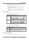
Table 5-7 Pin assignment of 4E1/4CE1 shielded twisted-pair cable ................................................................5-12
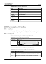
Table 5-8 Pin assignment of 8E1/8CE1 coaxial cable ......................................................................................5-14
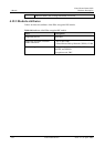
Table 5-9 Pin assignment of 8E1/8CE1/8CT1 shielded twisted-pair cable ......................................................5-16
Table 5-10 Pin assignment of the 16CE1 coaxial cable....................................................................................5-20
Table 5-11 Pin assignment of the 16CE1 shielded twisted-pair cable ..............................................................5-22
Table 5-12 Pin assignment of the V.24 DTE cable ...........................................................................................5-27
Table 5-13 Pin assignment of the V.24 DCE cable ...........................................................................................5-28
Table 5-14 Pin assignment of the V.35 DTE cable ...........................................................................................5-29
Table 5-15 Pin assignment of the V.35 DCE cable ...........................................................................................5-29
Table 5-16 Pin assignment of the DTE-to-DCE cable (HSSI interface cable) .................................................5-30
Table 5-17 Pin assignment of the DTE-to-DTE cable (null modem cable)......................................................5-33