


Nortel Secure Router 8012
Hardware Description 5 Cables
Issue 5.3 (6 April 2009) Nortel Networks Inc. 5-25
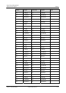
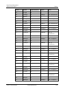
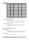
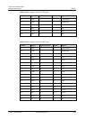
DB78 Signal Signal direction Signal RJ45
11 CABLE_TY
PE_SEL1
ÅPGND — —
20 PGND — — —
21 PGND — — —
30 PGND — — —
39 PGND — — —
40 PGND — — —
49 PGND — — —
50 PGND — — —
59 PGND — — —
60 PGND — — —
69 PGND — — —
78 PGND — — —
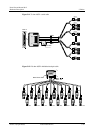
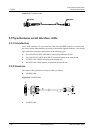
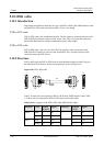
5.7.4 4CT1/8CT1 interface cable
The 4CT1/8CT1 interface module of Secure Router 8012 is connected with the 120-ohm
shielded twisted-pair cable.
Figure 5-8 shows the outline of the 4CT1 cable and Table 5-7 shows the pin assignment.
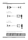
Figure 5-10 shows the outline of the 8CT1 cable and Table 5-9 shows the pin assignment.
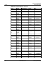
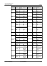
5.7.5 16CT1 interface cable
The 16CT1 interface cable for the Secure Router 8012 is a 120-ohm shielded twisted-pair
cable.
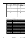
Figure 5-12 shows the outline of the 16CT1 cable and Table 5-11 shows the pin
assignment.
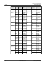
5.8 Channelized E3 interface cable
5.8.1 Introduction
The 1CE3 interface module provides two SMB interfaces, which are connected to the Tx end
and Rx end of the peer device. The interfaces work in 75-ohm unbalanced transfer mode and
are connected with the peer device through a pair of 75-ohm unbalanced coaxial cables.
5.8.2 Structure
Figure 5-13 shows the outline of the 1CE3 interface cable.