


Nortel Secure Router 8012
Hardware Description 4 Boards
Issue 5.3 (6 April 2009) Nortel Networks Inc. 4-5
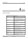
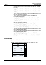
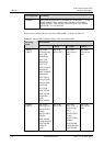
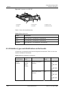
Figure 4-2 Arrangement of the Secure Router 8012 slots on the backplane (rear view)
NPU1
PWR2
PWR1
FAN
NPU2
You can insert the RPU into slots 9 and 10 on the top of the front panel of the chassis. You can
insert the NPU into the two slots on the top of the rear panel of the chassis. The slots for
NPUs and RPUs are positioned back to back.
You can insert an FIC into any of the slots 1 to 8.
You can insert an HIC into any of the slots 1, 2, 3, 4, 5, and 7. The type of HIC, however, is
determined by the working mode of the router.
The Secure Router 8012 can operate in two modes: ordinary mode and extended mode. For
information about the differences between the two modes, see
Table 4-1.
Before hot swapping, run the preplug slot Existing slot number command in the system view.
When information appears indicating that hot swapping is permitted, you can insert or remove
boards. Nortel recommends that you substitute the same type of boards during hot swapping.
z
To switch from ordinary mode (3HIC) to extended mode (6HIC), first remove the
non-extendable HIC from slot 1. Otherwise, you cannot switch from ordinary mode to
extended mode.
z
To switch from extended mode (6HIC) to ordinary mode (3HIC), first remove the
extendable HICs from slots 1, 3, 5, and 7. Otherwise, you cannot switch from extended
mode to ordinary mode.
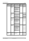
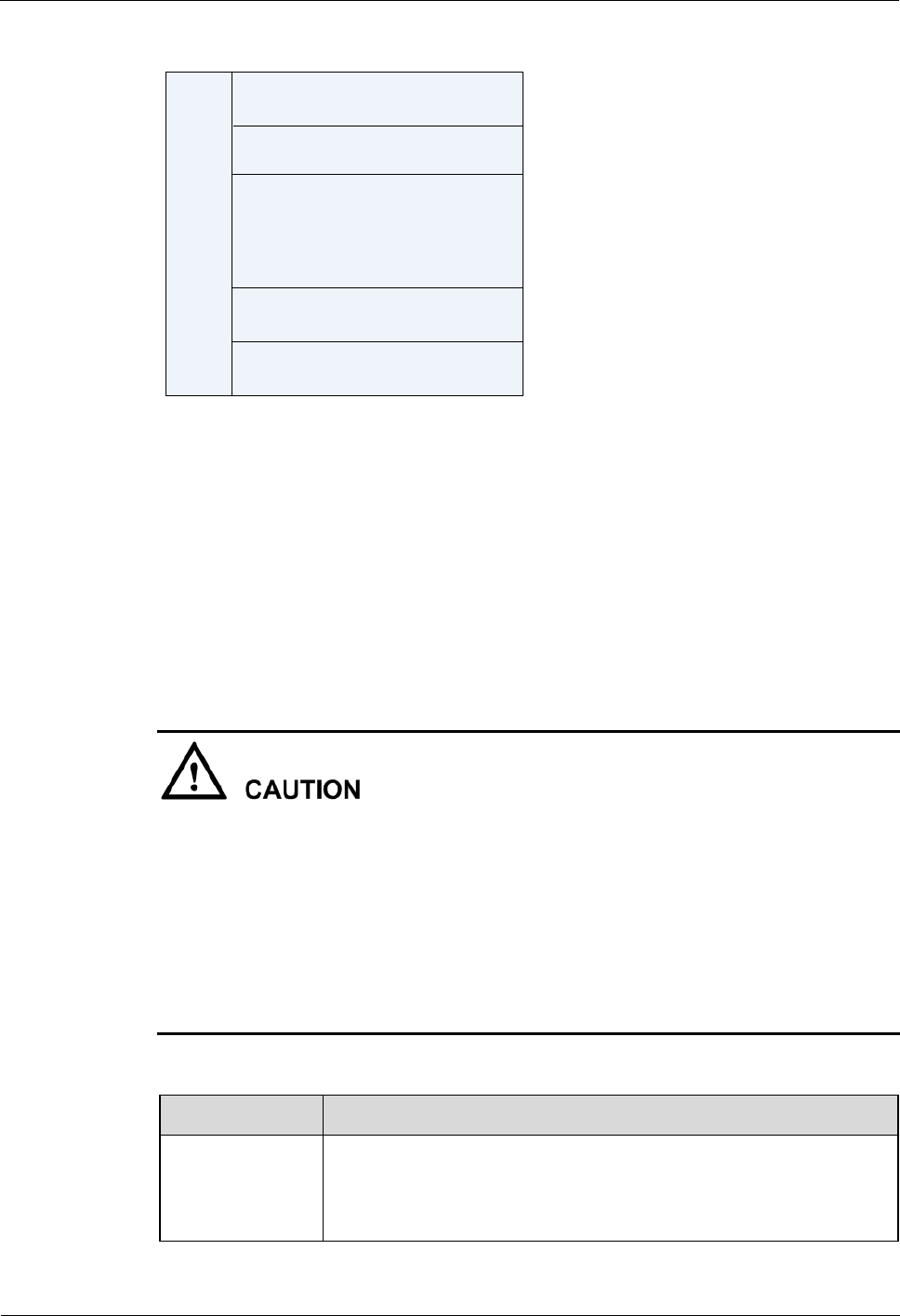
Table 4-1 Working modes of the Secure Router 8012
Working mode Condition
Ordinary One of the following HICs is inserted in slot 1: 2xFE UTP, 4xFE
UTP, 8xFE UTP, 2xFE UTP, 4xFE UTP, 8xFE Optical, 1xGig E
(SFP), 2xGig E (SFP), 2x155 POS, 4x155 POS, 2xOC3/STM1,
4xOC3/STM1 ATM (HIC) (SFP), or IPSec Module.