


9
ASSEMBLY
FOR YOUR OWN SAFETY, DO NOT CONNECT THE MACHINE TO THE POWER SOURCE UNTIL
THE MACHINE IS COMPLETELY ASSEMBLED AND YOU READ AND UNDERSTAND THE ENTIRE
INSTRUCTION MANUAL.
MOTOR BRACKET
TO STAND
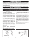
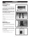
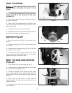
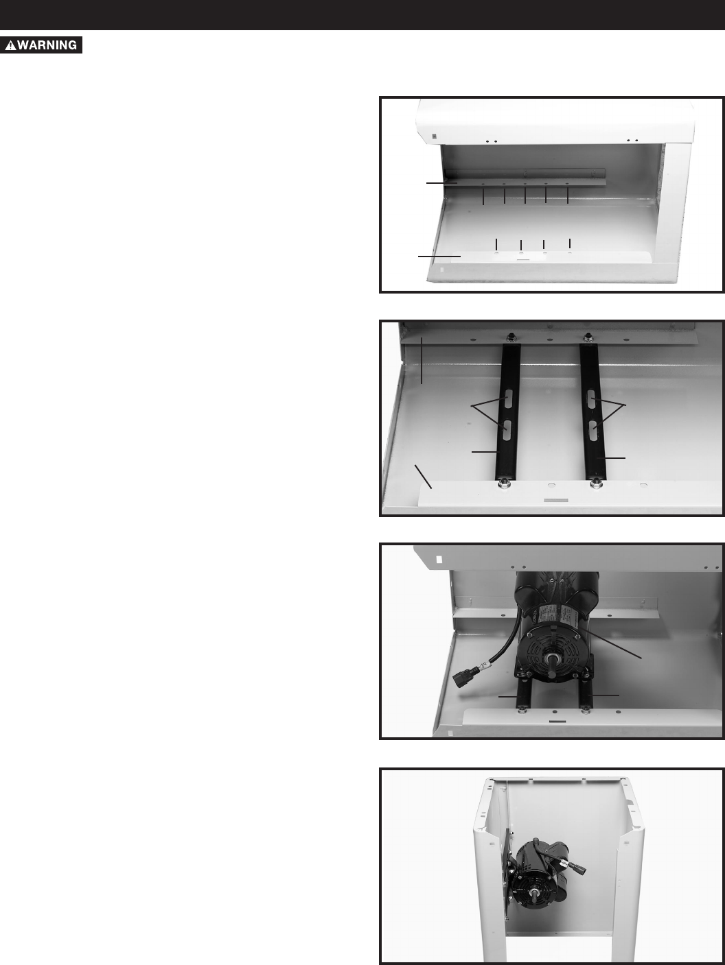
1. Place the stand base on its side as shown in Fig. 6.
Fig. 6
2. Align the two holes in the motor bracket (A) Fig. 7,
with the two holes in the stand. NOTE: ATTACH
MOTOR BRACKETS TO HOLES #1 AND 3 IN FRONT
STAND FLANGE (D) FIG. 6, AND HOLES #2 AND 4 IN
BACK STAND FLANGE (E).
NOTE: MAKE SURE THE SLOTS (C) FIG. 7, IN THE
MOTOR BRACKET (A), ARE POSITIONED CLOSER
TO THE OPENING OF THE STAND (D) THAN THE
BACK PANEL (E) OF THE STAND.
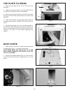
3. Insert a 5/16-18x3/4" carriage head bolt through the
hole in the motor bracket (A) Fig. 7, and the hole in the
stand.
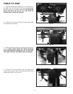
4. Thread a 5/16-18 hex nut onto the screw and tighten
securely.
5. Repeat this process for the remaining hole in the
motor bracket.
6. Attach the other motor bracket to the stand in the
same manner.
Fig. 7
MOTOR TO
MOTOR BRACKET
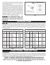
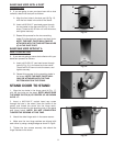
1. Place the motor (A) Fig. 8, on the motor brackets (B).
Align the holes in the motor with the holes on the motor
bracket.
2. Insert a 5/16-18x3/4" carriage head bolt through the
hole in the motor bracket and the hole in the motor.
3. Thread a 5/16-18 hex nut on to the screw. NOTE:
DO NOT COMPLETELY TIGHTEN THE BOLT AND
NUT AT THIS TIME.
4. Repeat this process for the three remaining holes in
the motor and motor bracket.
5. Place stand on its base as shown in Fig. 9.
Fig. 8
Fig. 9
1
2
3
4
1
2
3
4
5
D
E
E
D
A
A
C
C
A
B
B