


14
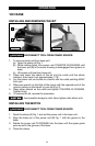
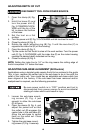
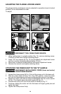
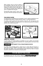
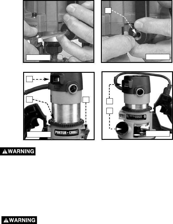
ADJUSTING THE PLUNGE LOCKING LEVER
The plunge-locking mechanism may be adjusted to reposition lever (in locked
position), or to compensate for wear.
To adjust:
DISCONNECT TOOL FROM POWER SOURCE.
1. While holding lever in upright position (Fig. 14), remove retaining screw.
Continue to hold lever through remaining steps.
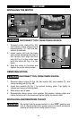
2. Insert 1/8" hex wrench (A) Fig. 15 (not furnished) into adjustment screw
and turn counter-clockwise approximately 1/2 turn.
3. Move lever to desired locked position and tighten adjustment screw.
4. Remove hex wrench and replace retaining screw.
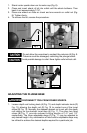
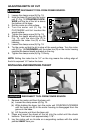
ATTACHING THE POWER UNIT TO THE “D” HANDLE
DISCONNECT BOTH POWER CORDS (base and motor)
FROM POWER SOURCE.
1. Loosen the clamp screw (A) Fig. 16 to set the power unit in the base unit.
2. With the motor switch (C) Fig. 16 in the “ON” position, insert the motor
unit into the base aligning the lower pin (B) with the groove in the base.
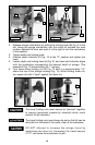
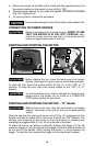
3. Rotate the motor unit into the base CLOCKWISE until the motor switch
(A) Fig. 17 is directly above the knob handle (B) Fig. 17.
4. Connect the motor unit cord to the outlet in handle (C) Fig. 17.
5. Continue rotating the motor unit into the base until upper guide pins set
rigidly into base.
6. Tighten the clamp screw firmly.
Fig. 14
Fig. 15
Fig. 16
Fig. 17
A
C
B
A
A
B