


15
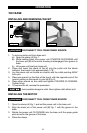
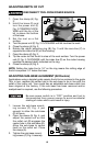
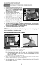
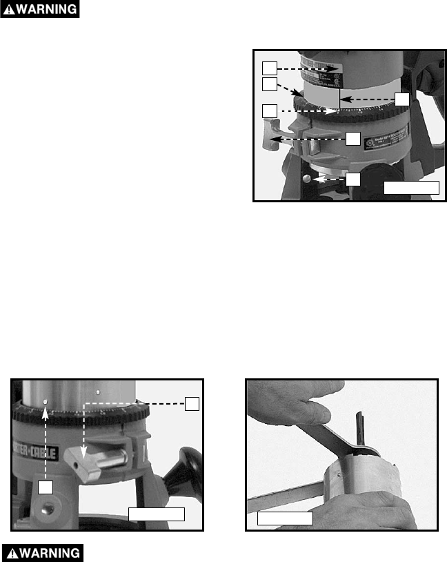
ADJUSTING DEPTH OF CUT
DISCONNECT TOOL FROM POWER SOURCE.
1. Loosen the clamp screw (A) Fig. 18.
2. Hold the base (E) and turn the motor
unit (F) Fig. 18 COUNTER-CLOCK-
WISE until the tip of the bit is above
the bottom of the base.
3. Set the router on a flat surface.
4. Turn the motor unit (F) Fig. 18
CLOCKWISE until bit touches the
wood surface.
5. Tighten the clamp screw (A) Fig. 18.
6. Rotate the depth adjusting ring (B)
Fig. 18, until the zero-line (C) is
opposite the index line (D) on the
housing.
7. Loosen the clamp screw (A) Fig. 18.
8. Tip the router so that the bit is clear of the wood surface. Turn the motor
unit (F) Fig. 18 CLOCKWISE until the index line (D) on the motor housing
reaches the desired depth indicated on the ring.
9. Tighten the clamp screw (A) Fig. 18 firmly.
NOTE: Setting the index line to 1/4" on the ring means the cutting edge of
the bit is exposed 1/4" below the base.
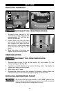
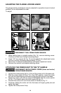
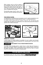
INSTALLING AND REMOVING THE BIT
DISCONNECT TOOL FROM POWER SOURCE.
1. Remove the motor unit from the base unit:
(a) Loosen the clamp screw (A) Fig. 19.
(b) While holding the base, turn the motor unit COUNTER-CLOCKWISE
until the lower pin (B) in the motor housing is disengaged from the
groove in the base.
(c) Lift the motor unit from the base unit.
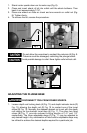
2. Clean and insert the shank of the bit into the collet until the shank
bottoms. Then back it out approximately 1/16".
3. Lay the motor unit on its side on a supporting surface with the collet
pointed AWAY from you.
Fig. 18
D
F
B
C
A
E
A
B
Fig. 19
Fig. 20