


11
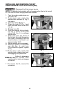
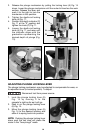
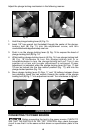
1. Loosen the sub-base mounting screws (C) Fig. 7 just enough to allow
the sub-base (D) to move.
2. Open the clamp (A) Fig. 7, and adjust the power unit so that the collet
nut (B) engages the center hole in the sub-base (D). Allow the sub-base
to center itself on the collet nut. Close the clamp (A).
3. Tighten the sub-base mounting screws (C) Fig. 7 securely.
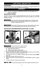
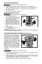
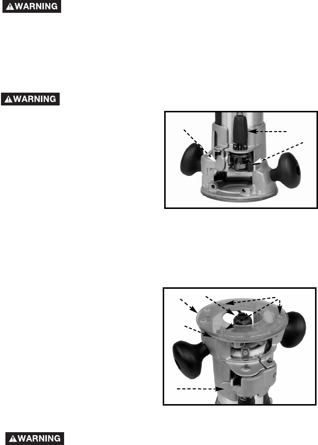
INSTALLING THE MOTOR
Disconnect tool from power source.
1. Open the clamp (A) Fig. 1 and set the power unit in the base unit.
2. Align the rack and pin (C) Fig. 1 of the power unit with the grooves in
the base, pull the lever (B) Fig. 1, and lower the motor into the base.
3. Close the clamp (A).
4. Reverse the procedure to remove.
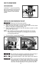
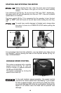
ADJUSTING SUB-BASE ALIGNMENT (All Routers)
Applications using a templet guide
require the bit to be centered in
the guide. This, in turn, requires
the center hole in the sub-base to
be in line with the collet of the
motor unit. Your model has an
adjustable sub-base which has
been aligned at the factory. The
fixed-base router comes with the
large hole (Fig. 7). To use templet
guides, use an accessory base,
and/or, if the sub-base has been
removed and readjustment is
required, use the following
procedure.
Fig. 7
A
B
C
D
E
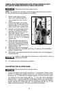
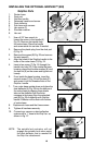
Disconnect tool from power source.
1. Open the clamp (A) Fig. 6.
2. Pull lever (B) and set router on
work so bit just touches it and
the router is flat and level.
3. While holding the lever (B), turn
depth knob (C) until zero lines up
with zero mark on router base.
4. Release lever (B), making sure
the zero stays lined up with
mark.
5. Close clamp (A).
6. Turn knob (C) clockwise to
desired depth of cut.
NOTE: Setting the index line to 1/16" on the knob means the cutting edge of the
bit is exposed 1/16" below the base.
Fig. 6
A
C
B
Disconnect tool from power source.
ADJUSTING DEPTH OF CUT