


15
OPERATION
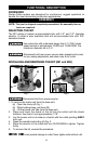
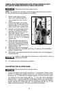
CONNECTING TO POWER SOURCE
Before connecting the tool to the power source, CHECK TO
SEE THAT THE SWITCH IS IN THE “OFF” POSITION. Also, check the power
circuit to see that it is the same as that shown on specification plate of the
tool.
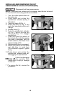
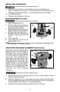
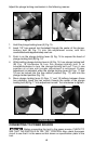
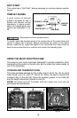
Adjust the plunge locking mechanism in the following manner:
1. Hold the plunge locking lever (A) Fig. 15.
2. Insert 1/8" hex wrench (not furnished) through the center of the plunge-
locking bolt (B) Fig. 15 into the adjustment screw, and turn
counterclockwise approximately one turn.
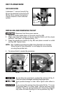
3. Push in on the plunge locking lever (A) Fig. 16 to expose the head of
plunge-locking bolt (B) Fig. 16.
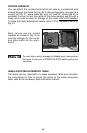
4. While holding plunge-locking lever in (A) Fig. 16, turn plunge-locking bolt
(B) Fig. 16 clockwise to turn the plunge-locking bolt in or
counterclockwise to turn the plunge-locking bolt out. Turn it one
position at a time until proper adjustment is achieved. Proper
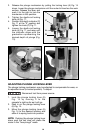
adjustment is indicated when the plunge-locking lever (A) Figs. 17 and
18 can be locked into the free motion position (Fig. 17), and into the
plunge-locked position (Fig. 18).
5. Move plunge locking lever (A) Figs. 17 and 18 halfway between those
two positions. Insert the hex wrench through the center of the plunge
locking bolt (B) Fig. 17 into adjustment screw. Turn clockwise to tighten.
Fig. 15
A
B
Fig. 16
A
B
Fig. 18
Fig. 17
A
A