


13
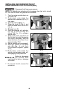
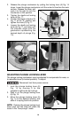
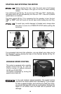
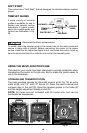
ADJUSTING THE PLUNGE BASE
Disconnect tool from power source.
1. Loosen the depth rod locking knob (A) Fig. 11, and depth indicator knob
(C) Fig. 11, allowing the depth rod (D) Fig. 11 to contact one of the turret
stops (A) Fig. 12. Normally the deepest desired cut is set with the depth
rod resting on the base casting (B) Fig. 11. The other three adjustable
stops (A) Fig. 12 may be adjusted to any desired height. Any combination
of fixed and/or adjustable stops may be utilized to achieve the desired
depths required for a particular job. The adjustable stop (B) Fig. 12 will
raise or lower that stop by 1/32" with one full turn of the stop.
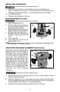
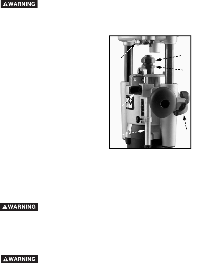
INSTALLING AND REMOVING BITS USING SPINDLE LOCK
ACTUATOR WHEN ROUTER IS TABLE-MOUNTED
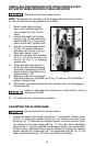
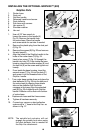
1. Reach under table and pull
down and rotate the spindle
lock actuator (E), Fig. 10 into
place.
2. Loosen the depth rod locking
knob (A) Fig. 10 and ensure the
depth rod (B) Fig. 10 is pushed
down all the way. Tighten knob.
3. Pull up on plunge locking lever
(C) Fig. 10, grab handles and
pull base up as far as it can go.
Push lever down to lock.
4. Push the spindle lock actuator
(E) Fig. 10 while turning the
chuck (D) Fig. 5 to engage
spindle lock.
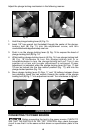
5. Clean and insert the shank of
the bit into the collet (loosening
the collet if necessary) until the
shank bottoms, then back it out
approximately 1/16".
6. Ensure spindle lock is engaged.
7. Place the wrench on the collet nut (F) Fig. 10 and turn CLOCKWISE to
tighten. Tighten firmly.
8. Push down and rotate the spindle lock actuator back out, disengaging
the spindle lock.
Failure to disengage the spindle lock could result in injury or
damage to the tool.
9. To remove the bit, reverse the procedure.
Disconnect tool from power source.
Fig. 10
A
B
C
D
E
F
NOTE: The spindle lock actuator will not engage when the tool is turned
on. Turn tool off when using spindle lock actuator.