


18
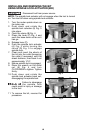
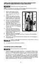
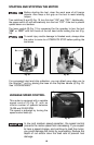
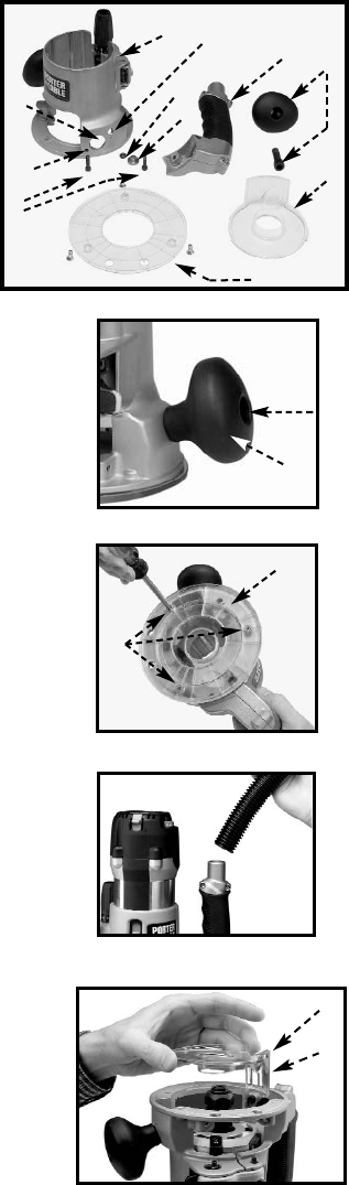
1. Use a 5/16" hex wrench to
loosen the screw in the handle (A)
Fig. 25. Remove the handle from
the router base. Place the handle
and screw aside for use later if needed.
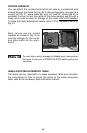
2. Remove the plastic plug from the dust port
(2) Fig. 24.
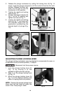
3. Remove the screws (B) Fig. 26 and remove
the sub-base (A).
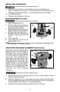
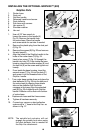
4. Align the holes of the GripVac handle to the
holes of the router base (10) Fig. 24.
5. Insert a hex screw (7) Fig. 24 through the
handle into hole (10). From inside the base
housing, place the shoulder washer (8) and
the hex nut (9) on the screw and tighten nut
loosely.
6. From inside the base housing, insert the
second screw (7) Fig. 24 into the hole (11)
and screw it into the threaded hole of the
GripVac handle.
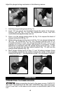
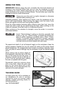
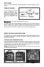
7. Turn router base upside down and place the
dust deflector (A) Fig. 28 into the bottom of
the router base by aligning three plastic
tabs on the deflector with the three
recesses in the base. Align the extended
part (B) Fig. 28 of deflector with GripVac
handle. Deflector will be flush with bottom
of router base.
8. Replace sub-base and the three screws.
9. Tighten all hardware securely.
10. Connect any vacuum or dust collection
system with a 1" hose to the Grip Vac as
shown in Fig. 27.
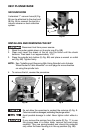
INSTALLING THE OPTIONAL GRIPVAC
™ (892)
GripVac
Parts
1. Router base
2. Dust port
3. GripVac handle
4. Removed handle and screw
5. Dust deflector
6. Sub-base with screws
7. Hex screw (2)
8. Shoulder washer
9. Hex nut
Fig. 25
A
SCREW
Fig. 26
Fig. 27
A
B
Fig. 24
1
2
3
4
5
6
7
9
8
NOTE: The spindle lock actuator will not
engage the spindle lock when using
the dust deflector that is needed for
the Grip Vac attachment.
Fig. 28
A
B
10
11