


5
UNPACKING AND CLEANING
Carefully unpack the machine and all loose items from the shipping container(s). Remove the protective coating from
all unpainted surfaces. This coating may be removed with a soft cloth moistened with kerosene (do not use acetone,
gasoline or lacquer thinner for this purpose). After cleaning, cover the unpainted surfaces with a good quality household
floor paste wax.
ASSEMBLY
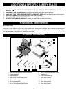
ASSEMBLY TOOLS REQUIRED
ASSEMBLY TIME ESTIMATE
Disconnect the machine from the power source and remove the blade guard before using the
tenoning jig. Reinstall the blade guard immediately after jig use is complete. Always unplug the
machine before removing or installing the blade guard.
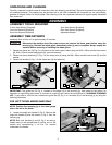
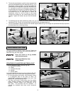
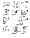
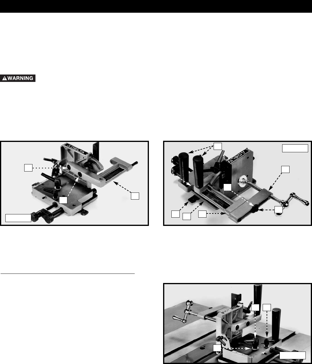
1. Fasten the clamp arm (A) Fig. 3 to the back of the work support plate using the M10 x 25mm socket head screw
(B), M10 x 25mm socket head screw (X), and lockwashers.
2. Fasten the clamp assembly (C) Fig. 4 to the clamp arm (A) using the M8 x 50mm socket head screw (D) and flat
washer.
3. Fasten the handles (F) Fig. 4 to the clamp arm (A) and base (H).
Fig. 3
Fig. 4
A
D
C
F
E
G
B
A
2.5mm Hex Wrench (Supplied)
3mm Hex Wrench (Supplied)
8mm Hex Wrench (Supplied)
4mm Hex Wrench (Supplied)
6mm Hex Wrench (Supplied)
Adjustable Wrench
Assembly time for this unit is approximately 30 minutes.
X
H
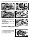
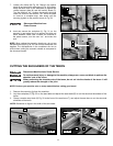
FOR LEFT-TILTING ARBOR SAWS ONLY
NOTE: Position the tenoning jig in the miter gauge
slot to the left of the blade.
4. Loosen the small lock handle (J) Fig. 5. Remove the
large lock handle (K) and flat washer (L) Fig. 5 from the
tenoning jig.
NOTE: Both lock handles (J) and (K) Fig. 5 are spring-
loaded and can be repositioned by pulling out on the
handle and repositioning it on the nut located
underneath the handle.
K
Fig. 5
L
J
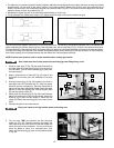
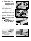
IMPORTANT: The guide bar (G) Fig. 4, located on the base (H) of the tenoning jig, was preset at the factory for
operation on right-tilting arbor saws. If your saw is a right-tilt saw, follow the instructions for “ALIGNING TENONING
JIG”. If your saw is a left-tilt saw, relocate the guide bar (G) Fig. 4 on the base (H) of the tenoning jig by using the
following directions.