


6
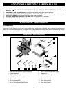
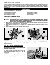
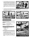
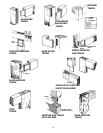
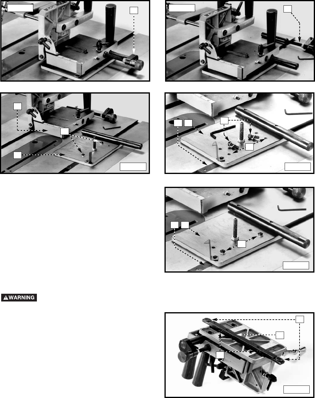
6. Use the supplied 3mm hex wrench to loosen the set screw (M) Fig. 6. Remove the micro-adjustment assembly (N) from
the tenoning jig (Fig. 7).
M
N
H
R
P
H
R
G
Fig. 6
Fig. 7
Fig. 8 Fig. 9
Fig. 10
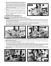
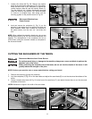
ADJUSTING THE GUIDE BAR TO THE TABLE SLOT
Disconnect Machine from Power Source
C
A
B
Fig. 11
7. Lift the jig assembly (P) Fig. 8 from the base (H).
Remove the two button head screws and flat washers
(R) from the base.
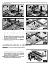
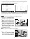
8. Slide the base (H) Fig. 9 forward until the two holes (S)
are aligned with the holes in the guide bar (G). Fasten
the base to the guide bar with the two button head
screws and flat washers (R) (Fig. 10).
9. Reassemble the items that were removed in STEPS 4,
5, and 6 in reverse order.
S
H
G
R
1. The tenoning jig is furnished with an adjustable guide
bar (A) Fig. 11 that allows the jig to custom-fit to your
saw, eliminating side-to-side play. Also, a T-slot washer
(B) is on each end of the guide bar (A) to keep the
tenoning jig from lifting during operation.
NOTE: Remove the T-slot washers (B) if your table saw is
not equipped with T-slotted miter gauge slots.