


7
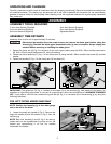
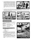
2. Place the tenoning jig guide bar (A) Fig. 12 into the left
miter slot (D) and slide the tenoning jig back and forth to
determine if it has side-to-side play. If the tenoning jig
slides easily through the miter slot without side-to-side
play, no adjustment is necessary. However, if the tenoning
jig fits too snugly, or if there is excessive play between the
guide bar (A) and the miter slot (D), adjust the jig, using
instructions 3-5 of this section.
3. Remove the jig from machine and place it upside down
(Fig. 11).
4. Use the 2.5mm hex wrench to turn the screws (C) Fig. 11
clockwise for a snug fit, or counter-clockwise for a looser
fit.
5. Insert the tenoning jig back into the miter slot of the
machine to determine if the fit is suitable, or if further
adjustment is required.
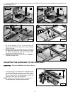
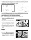
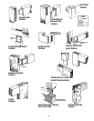
1. Place the tenoning jig guide bar (A) Fig. 12 into the left miter gauge slot.
2. Use a square (E) Fig. 12 to see if the vertical work support plate (F) is 90 degrees to the saw table. If an adjustment is necessary,
loosen the lock handle (G) and the set screw (H) Fig. 13, move the vertical work support plate (F) until it is 90 degrees to the
table, and tighten the lock handle (G).
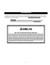
3. With the vertical work support plate (F) Fig. 13 adjusted, tighten the set screw (H) until it bottoms. This set screw (H) enables
you to rapidly position the vertical work support (F) 90 degrees to the table after it has been tilted.
4. Use a square (E) Fig. 14 to see if the face of the backstop (J) is 90 degrees to the saw table. If an adjustment is necessary,
loosen lock lever (K), adjust backstop (J) accordingly and tighten lever (K).
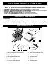
A
F
E
G
ALIGNING THE TENONING JIG
F
H
J
E
K
Fig. 12
Fig. 13
Fig. 14
D
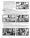
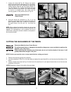
Disconnect Machine from Power Source
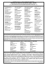
5. Loosen the nut (L) Fig. 15, and turn the set screw (M) counter-clockwise, two or three times.
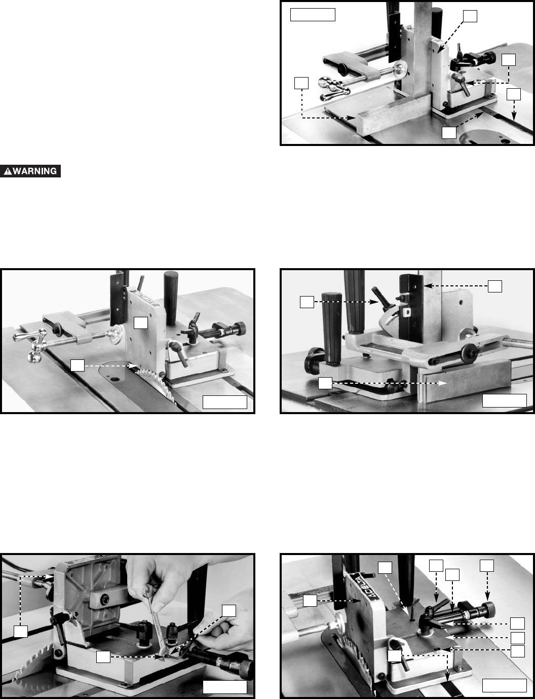
6. Loosen the two lock levers (N) and (P) Fig. 16, and move the jig (R) until the vertical work support plate (F) is against the saw
blade and tighten the lever (N).
NOTE: The lock levers (N) and (P) are spring-loaded and can be repositioned by pulling up on the handles and repositioning them
on the nut located underneath the handles.
7. Check to see if the vertical work-support plate (F) Fig. 16 is parallel to the saw blade.
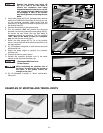
8. If an adjustment is necessary, loosen the lever (N) Fig. 16. Rotate the knob (S) clockwise as far as possible to align the holes
(T) with the guide bar (X) and to gain access to the set screws. Loosen the two screws inside the holes (T) and move the jig (R)
until the vertical work-support plate (F) is parallel to the saw blade. Tighten the two screws inside the holes (T).
9. Move the jig (R) Fig. 16 1/8" away from blade so that the vertical work-support plate (F) clears saw blade. Tighten the lever (N).
10. Rotate the knob (S) Fig. 16 counter-clockwise until the collar (V) is halfway between the knob (S) and the side of the jig (R);
tighten lever (P).
F
L
P
X
F
Fig. 15
Fig. 16
M
V
S
N
R
T
T