


10
Estimated Assembly Time: 10 - 20 minutes.
To avoid injury, make sure all parts are assembled
and adjusted properly before plugging the grinder
into a power outlet and turning it ON.
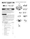
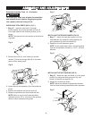
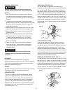
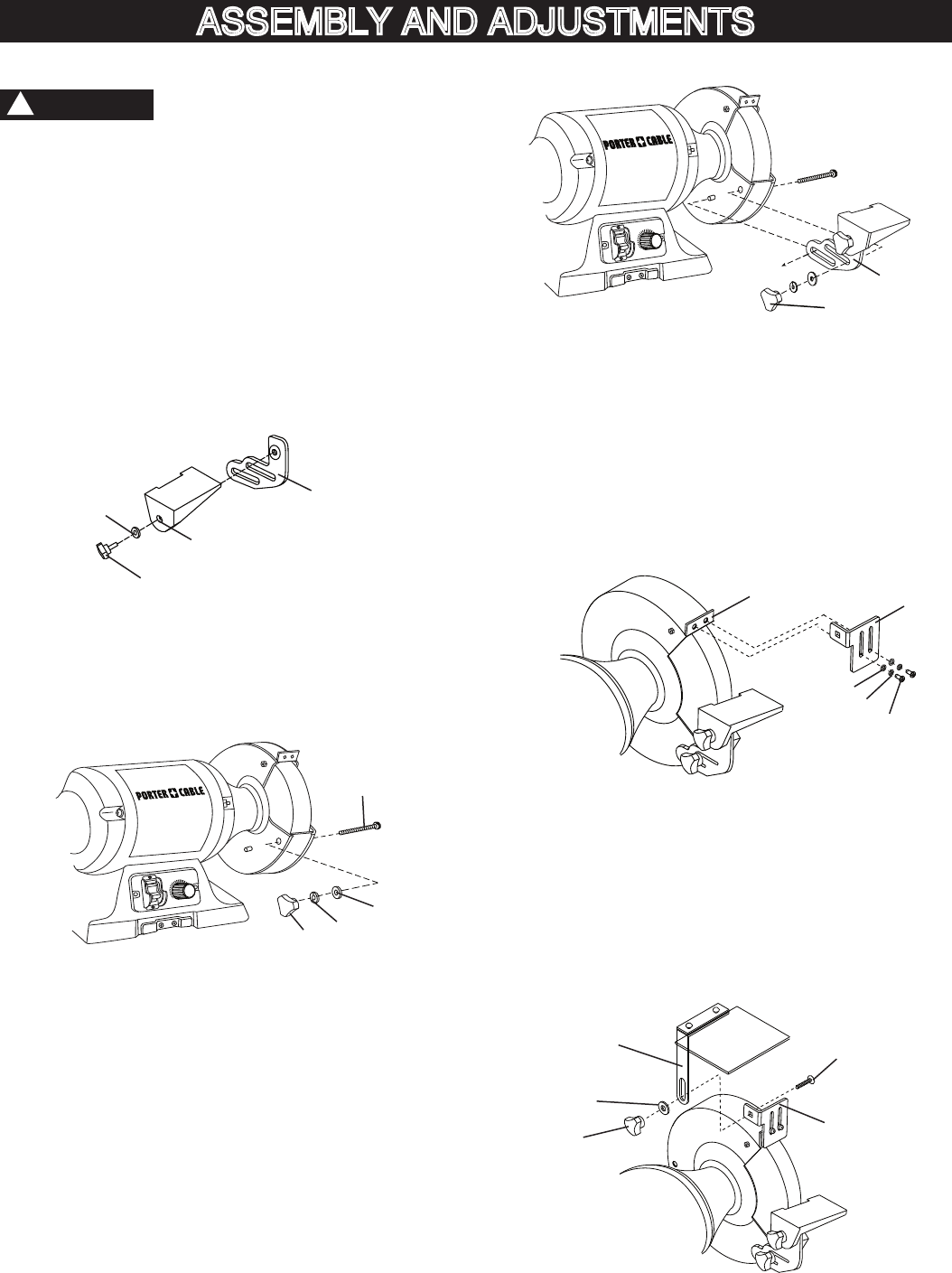
INSTALLING TOOL RESTS (FIG. A, B, C )
1. Bag “D” -
Insert the lock knob (1) through
the flat washer (2) and the right side tool rest (3)
to the right side tool rest mounting bracket (4) as
shown.
NOTE: The grooved tool rest mounts on the left side
of grinder.
Fig. A
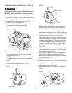
2. Remove the knob (5), lock washer (6) and flat
washer (7) from the carriage bolt (8) on the lower
portion of the wheel guard.
Fig. B
3. Attach the tool rest assembly (9) to the grinder as
shown.
4. Replace the washers and the lock knob (5).
5. Repeat the procedure for the left side tool rest.
NOTE: When in use, the tool rests should be
adjusted to within 1/8 in. (3.2 mm) of the grinding
wheel or other accessory being used.
ASSEMBLY AND ADJUSTMENTS
CAUTION
!
Fig. C
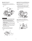
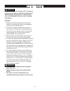
INSTALLING THE SPARK GUARDS (FIG. D)
1. Bag “F” - Attach the right spark guard (1) to the
extended pad (2) of guard by using the bolts (3),
spring washers (4) and flat washers (5).
2. Repeat for the left side spark guard.
NOTE: As the wheel wears down, the spark guards
must be re-adjusted to maintain a 1/16 in. (1.6 mm)
distance.
Fig. D
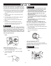
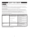
INSTALLING THE EYE SHIELDS (FIG. E)
1. Bag “D” - Attach the right eye shield (1) to the spark
guard (2) by using the locking nut knob (3), lock
washer (4) and the carriage bolt (5).
2. Repeat for left side eye shield.
NOTE: Adjust eye shields to appropriate distance
from tool rests avoiding interference when operation.
Fig. E
9
O
N
O
F
F
L
H
5
1
2
5
4
3
O
N
O
F
F
L
H
5
6
7
8
1
2
3
4
5
1
4
3
2