


11
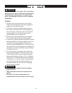
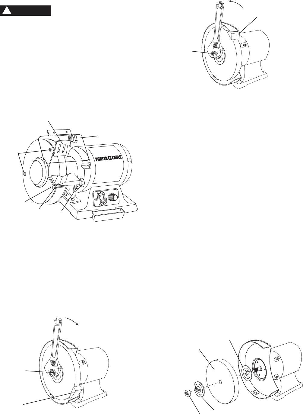
Fig. G-1
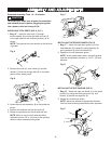
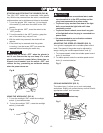
NOTE: The nut on the right side of the grinder has
a standard right-hand thread (turn counterclockwise
to loosen). The one on the left side has a left-hand
thread (turn clockwise to loosen). Both wheel nuts
tighten when turning toward the rear of the grinder and
loosen when turning toward the front of the grinder.
6. Inspect the wheel (10) for cracks, chips or any
other visible damage (other than normal wear) and
discard if such damage is found. Inspect the blotter/
cardboard disc for damage. If the blotter is missing
or severely damaged, replace it with a piece of thin
cardboard or blotter paper cut in the same shape.
NEVER USE A GRINDING WHEEL WITHOUT A
BLOTTER.
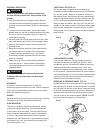
7. Install the new wheel or other accessory. Make sure
both wheel flanges (9) are in place with the concave
sides toward wheels. (Fig. H)
8. Place a wood wedge (7) (not supplied) between the
wheel and the wheel cover as shown in Fig. G-1.
NOTE: Do not overtighten the nut as this can crack
the grinding wheel (10).
9. Replace the wheel cover and screws.
10. Adjust the tool rest to 1/8 in. (3.2 mm) away from the
wheel and tighten securely.
11. Reattach and adjust the eye shield to a point
between your eyes and the wheel.
12. Set the spark guard 1/16 in. (1.6 mm) away from the
wheel.
Fig. H
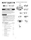
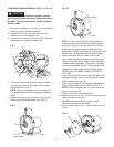
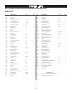
CHANGING GRINDING WHEELS (FIG. F, G, G-1, H)
Turn off and unplug the bench grinder. Use only
grinding wheels that measure 8 inches (200 mm) in
diameter. This tool has 5/8 inch (15.88 mm) arbors
on both sides.
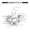
1. Raise the eye shield (1) out of the way and place the
spark guard (6) in its highest setting.
2. Loosen the knob (2) and remove the tool rest
assembly (3) and carriage bolt (4).
3. Remove the two screws (5) from the left side wheel
cover and then remove the outer cover.
Fig. F
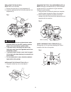
4. To prevent wheel rotating, place a wood wedge (7)
(not supplied) between the wheel and the wheel
cover as shown in Fig. G.
NOTE: Using a metal object, like a screwdriver, is
not recommended as it may damage the grinding
wheel.
5. Remove the hex nut (8) (as shown in Fig. G), the
wheel flange (9) and the wheel (10). (Fig. H)
Fig. G
CAUTION
!
9
9
8
10
Loosen
7
Wood wedge
8
Tighten
7
Wood wedge
8
ON
OFF
L
H
5
1
3
2
4
6