11
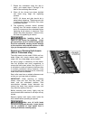
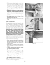
7. Rotate the cutterhead using the belt or
pulley, and repeat steps 2 through 6 for
each of the remaining three knives.
8. When all four knives have been installed
and made snug, begin the tightening
process.
NOTE: All knives and gibs should be in
place before tightening. Tightening one knife
in without the others in position can cause
cutterhead distortion.
9. The tightening process should proceed
working from the center outward on each
knife. Go once around the cutterhead further
tightening all gib screws in sequence. Then
repeat the same sequence a second time,
this time fully tightening all screws.
After installing knives, re-
check all gib screws for tightness. Loose
gib screws can result in knives being thrown
from the cutterhead, causing severe damage
to the machine and possible serious or fatal
injury to the operator or bystanders.
Replacing or Rotating Knife Inserts
(Helical Cutterhead only)
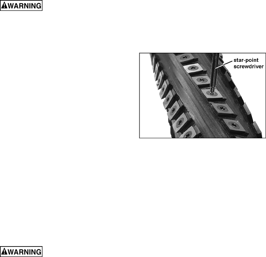
The knife inserts on the model 201HH are four-
sided. When dull, simply remove each insert,
rotate it 90° for a fresh edge, and re-install it.
No set-up gauge is necessary for the inserts.
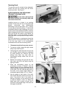
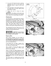
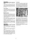
Use the provided star point screwdriver to
remove the knife insert screw. See Figure 10. It
is advisable to rotate all inserts at the same time
to maintain consistent cutting. However, if one
or more knife inserts develops a nick, rotate only
those inserts that are affected.
Each knife insert has an etched reference mark
so that you can keep track of rotations.
IMPORTANT: When removing or rotating
inserts, clean saw dust from the screw, the
insert, and the cutterhead platform. Dust
accumulation between these elements can
prevent the insert from seating properly, and
may affect the quality of the cut.
Before installing each screw, lightly coat the
screw threads with machine oil and wipe off any
excess.
Securely tighten each screw which holds the
knife inserts before operating the planer!
Make sure all knife insert
screws are tightened securely. Loose inserts
can be propelled at high speed from a
rotating cutterhead, causing injury.
Figure 10 – Model 201HH only


