


16
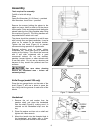
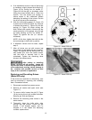
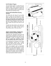
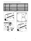
Anti-Kickback Fingers
The anti-kickback fingers (A, Figure 23) are an
important safety feature, as they help prevent
kickback of stock. They operate by gravity and
should be inspected frequently to make sure
they re free of gum and pitch, so that they move
independently and operate correctly.
Infeed and Outfeed Roller Spring
Tension
The infeed roller (B, Figure 23) and outfeed
roller (F, Figure 23) are those parts of your
planer that feed the stock while it is being
planed. The infeed roller and the outfeed roller
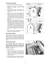
are under spring tension and this tension must
be sufficient to feed the stock uniformly through
the planer without slipping but should not be so
tight that it causes damage to the board. The
tension should be equal at both ends of each
roller.
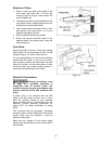
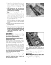
To adjust the spring tension of the infeed and
outfeed rollers, turn screws (Figure 24) with a
hex wrench. Turn screws on both ends of
infeed/outfeed rollers in the same manner.
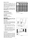
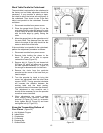
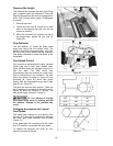
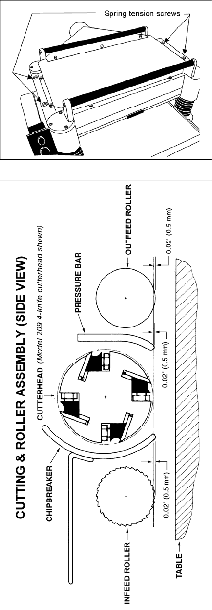
Height of Infeed Roller, Chipbreaker,
Pressure Bar and Outfeed Roller
The infeed roller, chipbreaker, pressure bar and
outfeed roller are adjusted at the factory. The
height relationship between these items and the
cutterhead is crucial for accurate and safe
planing. The infeed roller, chipbreaker, pressure
bar, and outfeed roller should be set .020"
(0.5mm) below the cutting circle. See Figure 25.
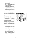
If any adjustments are necessary for the infeed
roller, chipbreaker, pressure bar or outfeed
roller, they should be done carefully. Use the
following steps as an example of procedure.
NOTE: This procedure uses a home-made
gauge block and feeler gauges, which should be
sufficient for most planer operations. If extra
precise measurements are desired, however,
use a dial indicator device. A bed and feed roller
gauge with dial indicator (stock # 2230002) is
available as an accessory for this machine, and
may be purchased from WMH Tool Group.
Figure 24
Figure 25