


12
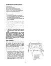
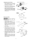
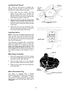
Handwheels and Lock Knobs
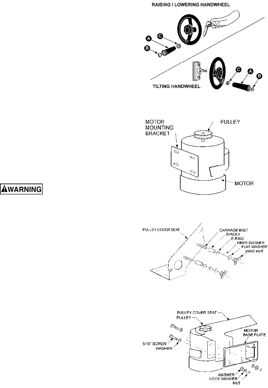
1. Attach handwheel knob (A) by inserting
screw (B) through hollow knob and into the
3/8" lock nut (C). See Figure 10. Lightly
screw assembly into handwheel.
2. Tighten the nut (C) to the handwheel just
enough so that there is adequate looseness
in the knob (A) to allow free rotation.
3. Attach the elevating and tilting handwheels
with lock knobs to the elevating and tilting
screws on the machine, as shown in Figure
10. Make sure the slot in both handwheels
engages with the roll pins in the elevating
and tilting screws.
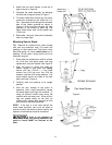
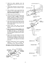
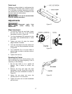
Mounting the Motor
Make sure motor is
disconnected from power source while
assembling the saw.
1. Carefully set motor on its end with the pulley
at the top, as shown in Figure 11.
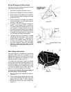
2. Install two 5/16-18 x 1-3/4 carriage bolts
through the holes in the pulley cover seat.
See Figure 12. Place a spacer over the bolt
shafts and temporarily install two 5/16 fiber
washers, two 5/16 wing nuts, and two E-
rings as shown.
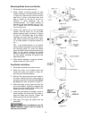
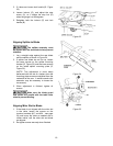
3. Lay the pulley cover seat on the motor as
shown in figure 13.
4. Install motor base plate with four 5/16-18 x 1
hex head screws, four 5/16 flat washers,
four 5/16 lock washers, and four 5/16 nuts,
with the screw heads on the motor side, as
shown in Figure 13. Slightly tighten two of
the nuts to temporarily secure components.
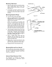
5. Assemble the motor base plate to the cast
motor bracket as shown in Figure 14. Slip
pin through and secure with the hex head
set screw.
IMPORTANT: Before mounting the motor
assembly to the saw, turn the trunnion
handwheel so that the saw blade is in the 90
degree vertical position (or the saw's pointer
is on the zero mark).
Figure 10
Figure 11
Figure 12
Figure 13