


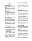

12
7.2 Voltage conversion
If 230V operation is desired, the following
instructions must be performed:
1. Disconnect machine from power source.
2. The drill press motor has four leads that are
factory connected for 115V operation. For
230V operation, reconnect the leads as shown
in diagram inside motor junction box cover.
Diagrams are also shown in section 14.0 of
this manual. (In case of discrepancy, diagram
inside junction box should take precedence.)
3. The 115V attachment plug supplied with the
drill press must be replaced with a UL/CSA
listed plug suitable for 230V operation, similar
to the plug illustrated in D, Figure 14. Contact
your local authorized Powermatic Service
Center or qualified electrician for proper
procedures to install the plug.
4. The drill press must comply with all local and
national codes after the 230-volt plug is
installed.
7.3 Extension cords
The use of extension cords is discouraged; try to
position equipment near the power source. If an
extension cord becomes necessary, be sure to use
one heavy enough to carry the current your product
will draw. An undersized cord will cause a drop in
line voltage resulting in loss of power and
overheating. Table 1 shows correct size to use
depending on cord length and nameplate ampere
rating. If in doubt, use the next heavier gauge. The
smaller the gauge number, the heavier the cord.
Ampere
Rating
Volts Total length of cord in feet
More
Than
Not
More
Than
120
240
25
50
50
100
100
200
150
300
AWG
00 06 18 16 16 14
06 10 18 16 14 12
10 12 16 16 14 12
12 16 14 12
Not
Recommended
Extension Cord Recommendations
Table 1
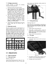
8.0 Adjustments
8.1 Table movement
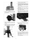
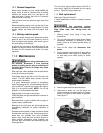
8.1.1 Raise and lower
Referring to Figure 15:
Loosen column locking handle (A, Figure 15). Turn
table elevating handle (B) to raise or lower table
along column rack. Re-tighten locking handle (A)
before attempting to drill.
Figure 15
8.1.2 Swing table away
Referring to Figure 15:
When drilling into a long workpiece, swing table out
of the way and use drill press base as your table.
Slots in the base can be used to mount work
holding devices.
1. Loosen column locking handle (A).
2. Swing table to desired position. If rack (C)
tends to bind, you will need to nudge the top or
bottom end of the rack around the column
while swinging table.
3. Tighten column locking handle (A).
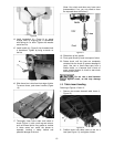
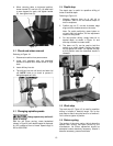
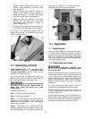
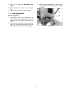
8.1.3 Tilt table
Referring to Figures 16 and 17:
1. To tilt table, slightly loosen bolt (D) and loosen
handle (E).
Figure 16
2. Pivot table to desired angle by aligning scale
on table to line on indicator plate (Figure 17).
3. Re-tighten bolt (D) and handle (E).