


15
clamps if needed. Bring the bit down until it
leaves a slight perforation in the board; then
raise it back up.
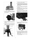
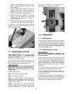
7. Use the socket head screw (I, Figure 23)
located toward back of laser assembly, to
adjust the cross hair. Turn screw as needed
until laser line (M) crosses perforation (L).
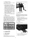
8. Adjust the other laser assembly in the same
manner until the laser lines form cross
hairs exactly over perforation in board, as
shown in Figure 24.
9. Re-check vertical alignment to ensure that the
laser lines did not shift during the procedure.
The laser is now calibrated properly and the
location of your holes can be centered at the cross
hairs for accurate drilling.
Figure 24
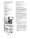
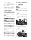
9.0 Operating controls
Power Indicator Light – The start switch has a
power indicator lamp which is on whenever there
is power connected to the Drill Press, not just
when the Drill Press is running.
Do not assume that no light means there is no
power to the machine. If the bulb is bad, there will
be no indication. Always check before use.
Do not rely that no light means
no power to the machine. Always check for
power first. Failure to comply may cause
serious injury.
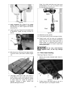
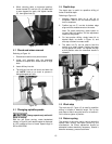
Referring to Figure 25:
Start – Pull out on the large red switch.
Stop – Push in the red switch.
Reset – If the Drill Press should stop without the
stop button being pressed, as the result of a
tripped fuse or circuit breaker, etc., push the red
switch back in to reset it.
Safety - The switch has a safety feature that
prevents unauthorized or accidental starting of the
drill press. With switch in "off" position, slide out the
safety key (A, Figure 25). This piece must be re-
inserted before the drill press can operate.
Figure 25
10.0 Operation
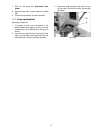
10.1 Installing bits
Insert bit (not provided) into chuck jaws with about
1” insertion. When using a small bit, do not insert it
so far that the jaws touch the flutes of the bit. Make
sure bit is centered in chuck before tightening
chuck. The chuck is a keyless model; simply rotate
it by hand to tighten the bit.
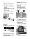
10.2 Positioning work piece
Whenever possible, use
clamps or work hold-downs to secure the work
piece to the table.
Always secure the work piece to prevent it being
torn from the operator’s hand. Using the column as
a work stop is not recommended; instead, use
holding devices such as clamps. When using the
table in tilted position, make sure the table is
securely tightened and the work piece is clamped
sufficiently.
For clean, splinter-free holes, place a piece of
scrap wood on the table below the work piece.
Perform operations with a minimum extension of
the quill. Adjust table position rather than using
excessive quill travel.
Feed bit into the material with only enough force to
allow the bit to work. Feeding too slowly may cause
burning of the work piece. Feeding too quickly may
cause the motor to slow and/or the bit to break.