


12
15
2
0
25
30
35
40
45
50
3
1
.
6
2
5
22.5
15
20
25
30
35
40
45
50
3
1.6
2
5
22.5
55
0
11
1
2
1
2
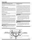
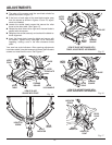
FEATURES
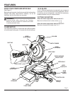
POSITIVE STOPS ON MITER TABLE
Positive stops have been provided at 0°, 11.25
°
,15
°
, 22.5
°
,
31.62
°
,and 45°. The 0°, 11.25
°
,15
°
, 22.5
°
, 31.62
°
,and 45° positive
stops have been provided on both the left and right side of the
miter table.
BEVEL LOCK KNOB
The bevel lock knob securely locks your compound miter
saw at desired bevel angles. Positive stop adjustment screws
have been provided on each side of the saw arm. These
adjustment screws are for making fine adjustments at 0
°
and
45
°
. Using the bevel override feature allows up to 48
°
for
bevel cuts.
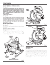
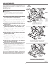
ELECTRIC BRAKE
An electric brake has been provided to quickly stop blade
rotation after the switch is released.
MITER FENCE
The miter fence on your compound miter saw has been
provided to hold your workpiece securely against when
making all cuts. The sliding miter fence on the left side is also
larger providing additional support.
The Repeat-A-Cut™ feature on both the left and right side
miter fences can be used when making repetitive cuts.
Simply mark the fence with a pencil, make the desired
number of cut(s), then wipe the mark off with a soft cloth.
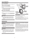
SELF-RETRACTING LOWER BLADE GUARD
The lower blade guard is made of shock-resistant, see-
through plastic that provides protection from each side of the
blade. It retracts over the upper blade guard as the saw is
lowered into the workpiece.
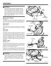
WARNING:
To avoid serious personal injury, always assure
saw is fully supported and securely attached to a
level work surface.
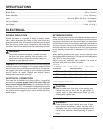
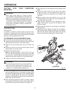
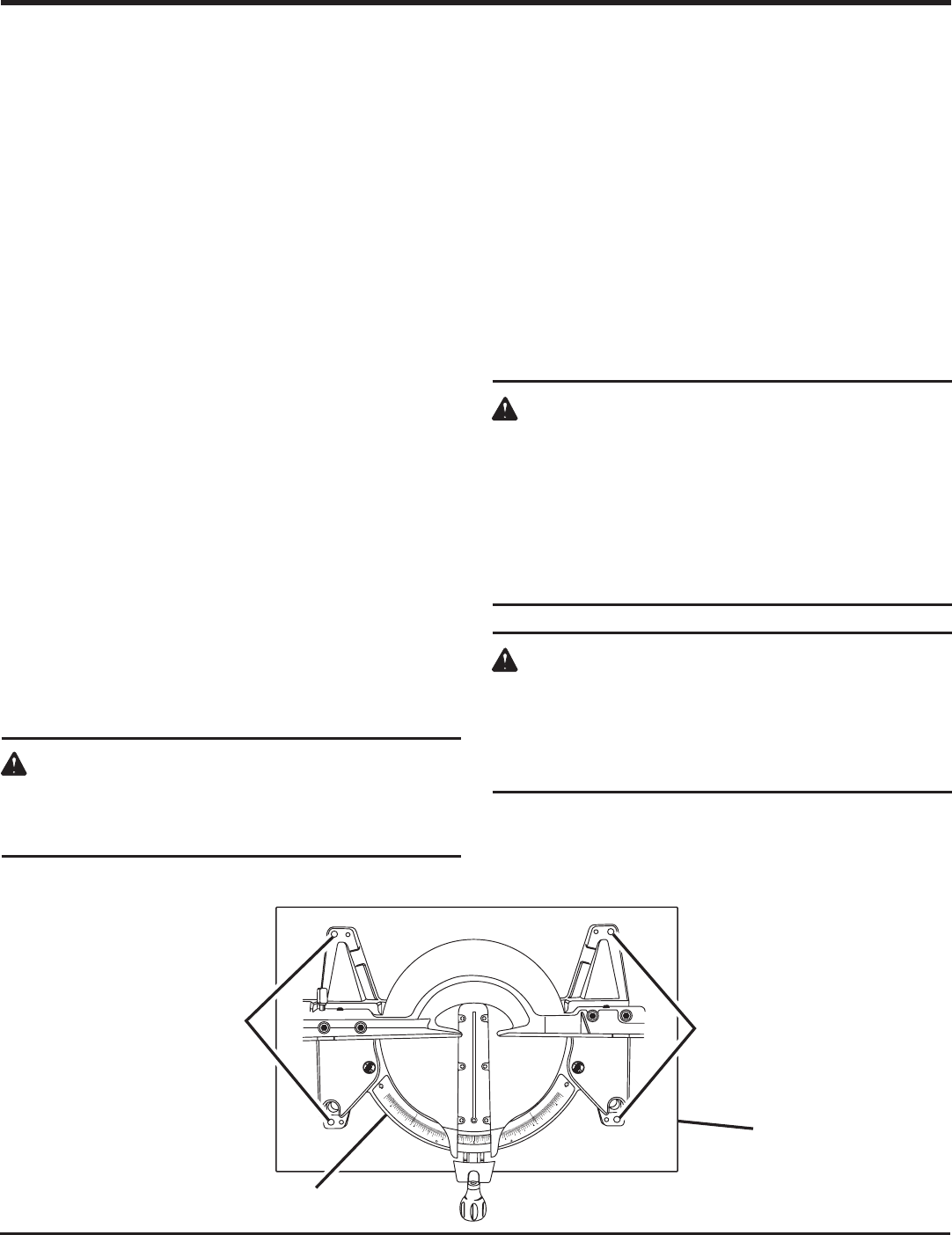
MOUNTING HOLES
See Figure 6.
Your compound miter saw should be mounted to a firm
supporting surface such as a workbench. Four bolt holes
have been provided in the saw base for this purpose. Each
of the four mounting holes should be bolted securely using
3/8 in. (10 mm) machine bolts, lock washers, and hex nuts
(not included). Bolts should be of sufficient length to
accommodate the saw base, lock washers, hex nuts, and the
thickness of the workbench. Tighten all four bolts securely.
The hole pattern is for an 18 in. x 24 in. (457 mm x 610 mm)
workbench. Carefully check the workbench after mounting
to make sure that no movement can occur during use. If any
tipping, sliding, or walking is noted, secure the workbench to
the floor before operating.
WARNING:
The operation of any saw can result in foreign ob-
jects being thrown into your eyes, which can result
in severe eye damage. Before starting power tool
operation, always wear safety goggles or safety
glasses with side shields and a full face shield
when needed. We recommend wide vision safety
mask for use over eyeglasses or standard safety
glasses with side shields.
WARNING:
Do not attempt to modify this tool or create acces-
sories not recommended for use with this tool. Any
such alteration or modification is misuse and could
result in a hazardous condition leading to possible
serious personal injury.
TRACE HOLES
AT THESE LOCATIONS
FOR HOLE PATTERN
TRACE HOLES
AT THESE LOCATIONS
FOR HOLE PATTERN
SAW BASE
Fig. 6
MOUNTING SURFACE