


LASER GUIDE
Make several practice cuts on different styles and thickness
of material.
Follow the directions below for using your Laser Guide.
Removing Your Mark:
Position the laser line near the left edge of your mark on the
work surface in order to remove the mark.
To Cut Your Mark:
Position the laser line near or over your mark on the work
surface in order to cut the mark.
To Leave Your Mark:
Position the laser line near the right edge of your mark on the
work surface in order to leave the mark.
After you have become familiar with using your Laser Guide,
you will be able to remove, cut, or leave your mark on the
work surface. Practice will teach you the correct position for
aligning the laser line with your mark.
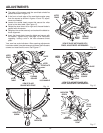
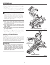
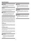
Fig. 34
BROKEN
RED LINE
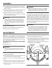
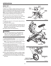
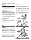
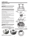
MOUNTING THE EXACTLINE™ LASER GUIDE
See Figure 33 .
Unplug your saw.
WARNING:
Failure to unplug your saw could result in accidental
starting causing possible serious personal injury.
See "To Install Blade" in the adjustments section of this
operator's manual.
Make sure inner blade washer is in place before posi-
tioning saw blade on the spindle of your saw.
Note: The laser guide replaces the outer blade washer.
Place the laser guide onto the spindle, aligning the double
"D" flats in the laser guide with the flats on the spindle.
Position flat surface of laser guide against the blade.
Warning labels are visible when laser guide is mounted
properly.
Depress spindle lock button and secure laser guide us-
ing blade wrench provided.
Note: The hex key bolt has left hand threads. Turn bolt
counterclockwise to tighten.
Using the blade wrench provided with your saw, tighten
bolt securely.
Return the blade wrench to the wrench storage area.
Replace the lower blade guard and blade bolt cover.
Retighten phillips screw securing blade bolt cover. Tighten
screw securely.
DANGER:
Laser radiation. Avoid direct eye contact with light
source.
OPERATION
See Figure 34.
The laser guide will generate a red colored line on the work
surface when the saw blade is spinning above 500 rpm. The
red laser line will appear as a broken line on the workpiece
when the blade assembly is in the uppermost position and
the motor switch is activated. This broken line will let you see
your mark and your laser guide line at the same time, and will
assist you in lining up your mark for more accurate cutting of
the workpiece.
ALIGNMENT
Align the laser line and your mark with the blade at the
uppermost position. Once both lines are in alignment, do not
move the workpiece until after you have finished cutting.
As the blade assembly is lowered toward the workpiece, the
broken line will become solid.
Fig. 33
BLADE
LASER
GUIDE
HEX KEY
BOLT
BLADE WRENCH
INNER BLADE
WASHER
SPINDLE
26