


20
OPERATION
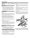
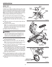
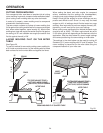
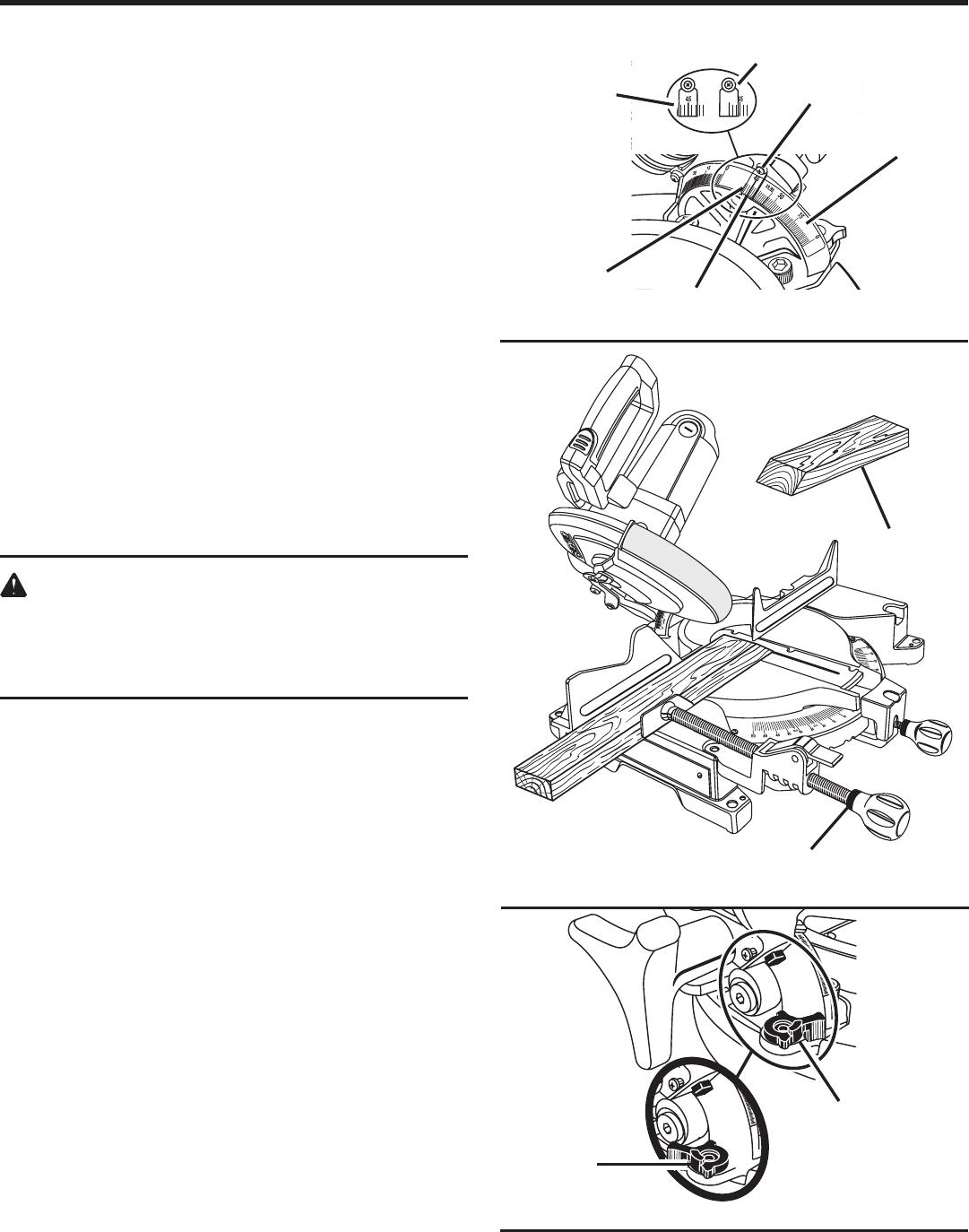
BEVEL CUT
See Figures 23 - 25.
A bevel cut is made by cutting across the grain of the
workpiece with the blade angled to the workpiece. A straight
bevel cut is made with the miter table set at the zero degree
position and the blade set at an angle between 0
°
and 48
°
.
Note: It may be necessary to adjust the sliding miter fence
to assure proper clearance prior to making the cut.
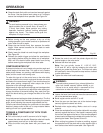
Pull out the lock pin and lift saw arm to its full height.
Loosen the miter lock handle. Rotate the miter lock handle
approximately one-half turn to the left to loosen.
Press the miter lock plate down with your thumb and
hold.
Rotate the control arm until the pointer aligns with zero
on the miter scale.
Release the miter lock plate.
Note: You can quickly locate zero by releasing the lock
plate as you rotate the control arm. The lock plate will
seat itself in one of the built-in positive stop notches,
located in the miter table frame.
Tighten the miter lock handle securely.
WARNING:
To avoid serious personal injury, always tighten the
miter lock handle securely before making a cut.
Failure to do so could result in movement of the
control arm or miter table while making a cut.
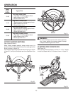
Loosen the bevel lock knob and move the saw arm to the
left to the desired bevel angle.
Bevel angles can be set from 0
°
to 48
°
.
See Figure 25.
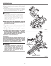
Note: Turn the bevel override clockwise to gain an extra
3
°
on the bevel angle (from 45
°
to 48
°
) of the cut.
Once the saw arm has been set at the desired angle,
securely tighten the bevel lock knob.
Place the workpiece flat on the miter table with one edge
securely against the fence. If the board is warped, place
the convex side against the fence. If the concave edge of
a board is placed against the fence, the board could
collapse on the blade at the end of the cut, jamming the
blade.
See Figures 30 and 31.
When cutting long pieces of lumber or molding, support
the opposite end of the stock with a roller stand or with a
work surface level with the saw table.
See Figure 28.
Align the cutting line on the workpiece with the edge of
saw blade.
Fig. 25
WORK CLAMP
BEVEL CUT
BEVEL
SCALE
INDICATOR
SCREW
SCALE
INDICATOR
Fig. 23
INDICATOR
POINT
SCALE
AT 45º
SCALE
AT 48º
POSITIVE STOP
ADJUSTMENT AT
45º
POSITIVE STOP
ADJUSTMENT AT 48º
Fig. 24