


18
ASSEMBLY
WARNING:
Make sure the spindle lock button is not engaged
before reconnecting saw into power source. Never
engage spindle lock button when blade is rotating.
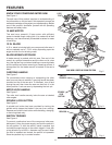
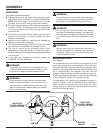
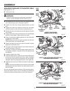
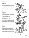
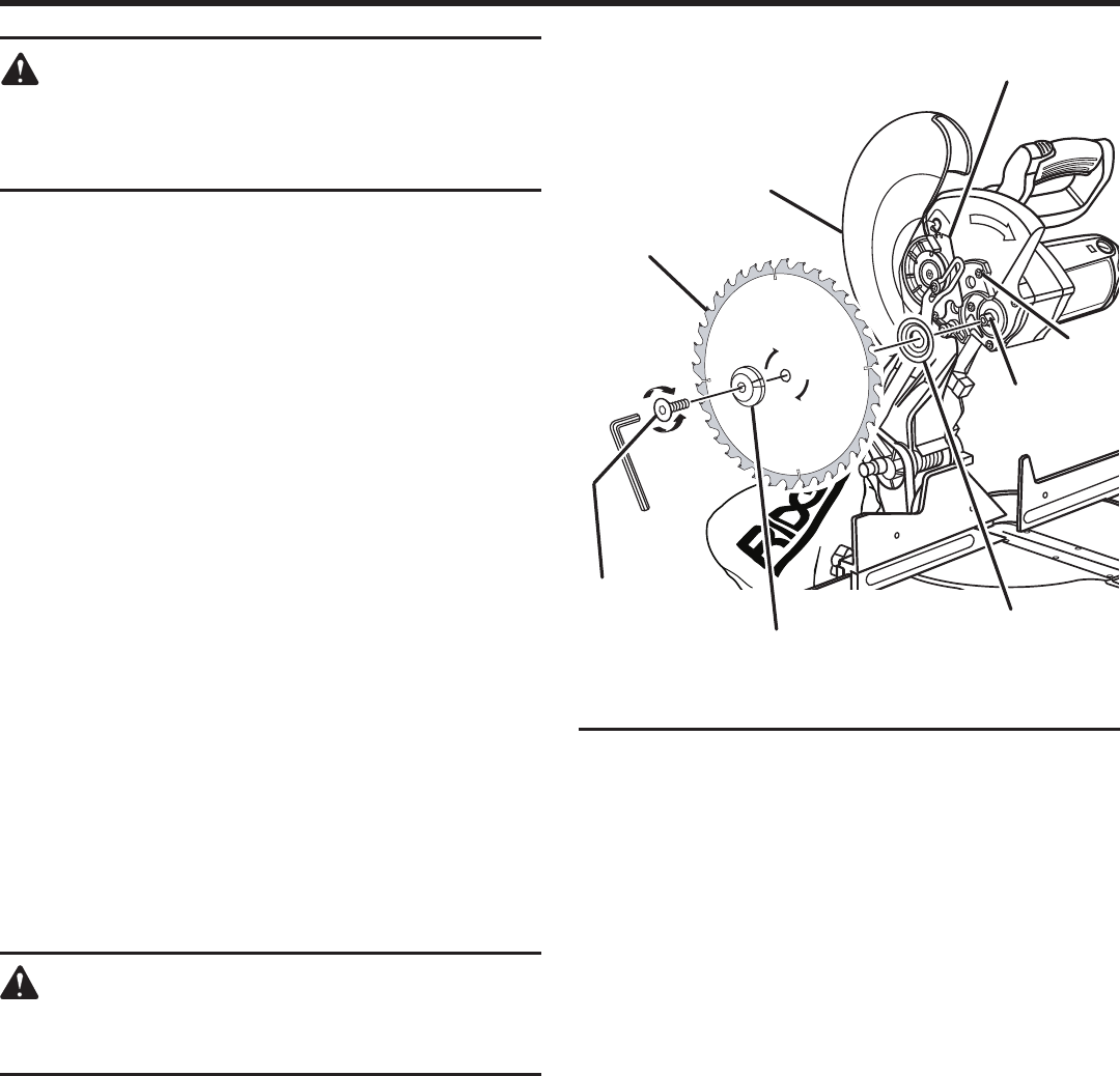
MOUNTING THE EXACTLINE™ LASER GUIDE
See Figure 15.
Unplug the saw.
See "To Install Blade" in the Assembly section of this
operator's manual.
Make sure inner blade washer is in place before
positioning saw blade on the spindle of the saw.
NOTE: The laser guide replaces the outer blade
washer.
Place the laser guide onto the spindle, aligning the double
"D" flats in the laser guide with the flats on the spindle.
Position flat surface of laser guide against the blade.
Warning labels are visible when laser guide is mounted
properly.
Depress spindle lock button and secure laser guide
using only the special hex bolt provided.
NOTE: The hex bolt has left hand threads. Turn bolt
counterclockwise to tighten.
Using the blade wrench provided with the saw, tighten
bolt securely.
Remove the blade wrench and store it in the saw base
for future use.
Replace the lower blade guard and blade bolt cover.
Retighten screw securing blade bolt cover. Tighten screw
securely.
DANGER:
Laser radiation. Avoid direct eye contact with light
source.
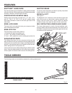
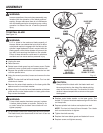
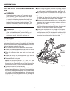
ALIGNING THE LASER GUIDE LINE
See Figure 16.
The laser guide will generate a red colored line on the work
surface when the blade is spinning. The red laser line will
appear as a broken line on the workpiece when the blade
assembly is in the uppermost position and the motor switch
is activated. This broken line will let you see your mark
and your laser guide line at the same time, and will assist
you in lining up your mark for more accurate cutting of the
workpiece.
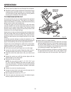
Align the laser line and your mark with the blade at the
uppermost position. Once both lines are in alignment, do not
move the workpiece until after you have finished cutting.
As the blade assembly is lowered toward the workpiece, the
broken line will become solid.
Make several practice cuts on different styles and thickness
of material.
1
0
1
5
2
0
2
5
3
0
3
5
4
0
4
5
5
0
LOWER
BLADE GUARD
BLADE
BLADE BOLT
COVER
FLATS
ON SPINDLE
INNER BLADE
WASHER WITH
DOUBLE "D" FLATS
LASER GUIDE
OR OUTER
BLADE WASHER
TO
LOOSEN
TO
TIGHTEN
HEX KEY
BOLT
Fig. 15
SCREW