


20
1
5
2
0
2
5
3
0
3
5
4
0
4
5
5
0
1
0
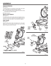
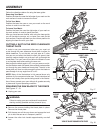
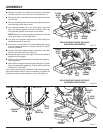
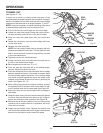
Depress the miter lock plate and rotate the miter table
until the pointer on the control arm is positioned at 0
°
.
Release the miter lock plate and securely tighten the miter
lock handle.
Remove the sliding miter fence by loosening the set screw
and the sliding miter fence knob.
Lay a framing square flat on the miter table. Place one
leg of the square against the fence. Slide the other leg
of the square against the flat part of saw blade.
NOTE: Make sure that the square contacts the flat part
of the saw blade, not the blade teeth.
The edge of the square and the saw blade should be
parallel as shown in figure 18.
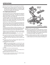
If the front or back edge of the saw blade angles away
from the square as shown in figures 19 and 20, adjust
-
ments are needed.
Loosen the socket head screws that secure the miter
fence to the miter table. See Figure 17.
Rotate the miter fence left or right until the saw blade is
parallel with the square.
Retighten the screws securely and recheck the blade-to-
fence alignment.
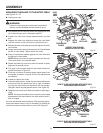
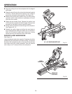
Insert the throat plate and secure with the screws. Tighten
firmly. See instruction regarding “Cutting a Slot in the Zero
Clearance Throat Plate”.
Your saw has several scale indicators. After squaring adjust
-
ments have been made, it may be necessary to loosen the
indicators screws and reset them to zero.
See Figure 21.
VIEW OF BLADE NOT SQUARE WITH FENCE,
ADJUSTMENTS ARE REQUIRED
Fig. 19
VIEW OF BLADE NOT SQUARE WITH FENCE,
ADJUSTMENTS ARE REQUIRED
Fig. 21
ASSEMBLY
INDICATOR
SCREW
SCALE
INDICATOR
MITER
SCALE
1
5
2
0
2
5
3
0
3
5
4
0
4
5
5
0
1
0
SLIDING
MITER
FENCE
MITER
TABLE
FRAMING
SQUARE
BLADE
SLIDING
MITER
FENCE
FRAMING
SQUARE
MITER
TABLE
BLADE
BEVEL
SCALE
INDICATOR
SCREW
SCALE
INDICATOR
INDICATOR
POINT
Fig. 20