


21
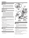
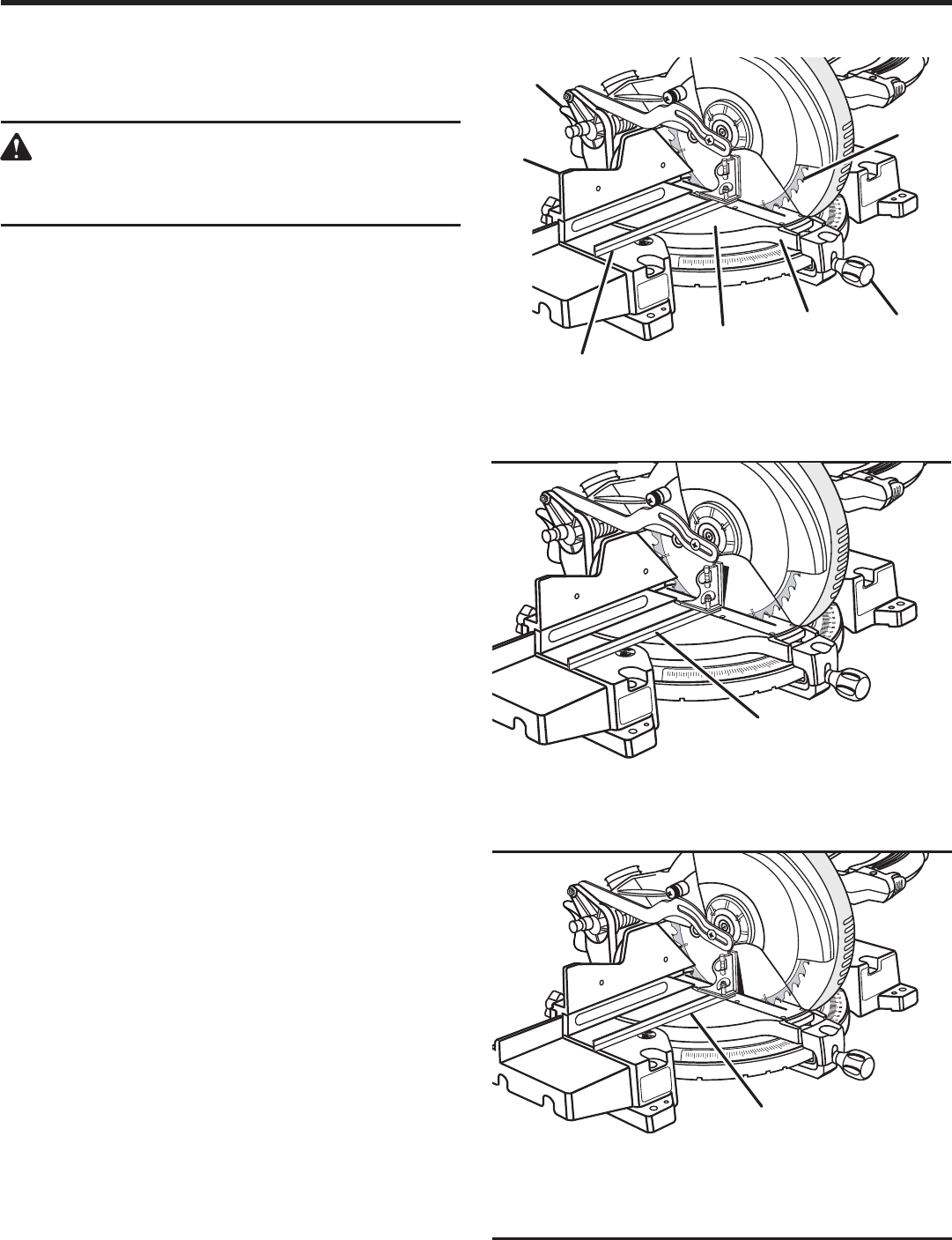
SQUARING THE BLADE TO THE MITER TABLE
See Figures 22 - 25.
Unplug your saw.
WARNING:
Failure to unplug your saw could result in accidental
starting causing possible serious personal injury.
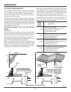
Pull the saw arm all the way down and engage the lock
pin to hold the saw arm in transport position.
Loosen the miter lock handle approximately one-half
turn.
Depress the miter lock plate and rotate the miter table
until the pointer on the control arm is positioned at 0
°
.
Release the miter lock plate and securely tighten the miter
lock handle.
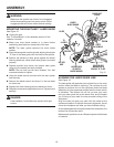
Loosen bevel lock knob and set saw arm at 0
°
bevel (blade
set 90
°
to miter table). Tighten bevel lock knob.
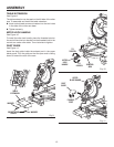
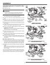
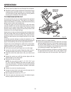
Place a combination square against the miter table and
the flat part of saw blade.
NOTE: Make sure that the square contacts the flat part
of the saw blade, not the blade teeth.
Rotate the blade by hand and check the blade-to-table
alignment at several points.
The edge of the square and the saw blade should be
parallel as shown in figure 22.
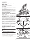
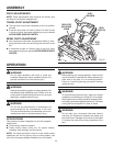
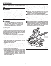
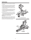
If the top or bottom of the saw blade angles away from
the square as shown in figures 22 and 24, adjustments
are needed.
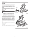
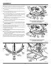
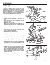
Loosen the bevel lock knob.
Using the blade wrench, loosen the bevel stop adjustment
screw and slide the bevel stop left or right as needed
to bring the saw blade into alignment with the square.
Retighten bevel stop adjustment screw. See Figure 25.
Retighten bevel lock knob. Recheck blade-to-table align-
ment.
NOTE: The above procedure can be used to check blade
squareness of the saw blade to the miter table at both 0
°
and 45
°
angles.
Your saw has several scale indicators. After squaring adjust-
ments have been made, it may be necessary to loosen the
indicators screws and reset them to zero. See Figure 21.
CORRECT VIEW OF BLADE
SQUARE WITH MITER TABLE
VIEW OF BLADE NOT SQUARE WITH MITER TABLE,
ADJUSTMENTS ARE REQUIRED
Fig. 24
VIEW OF BLADE NOT SQUARE WITH MITER TABLE,
ADJUSTMENTS ARE REQUIRED
Fig. 22
ASSEMBLY
1
5
2
0
2
5
3
0
3
5
4
0
4
5
5
0
1
0
BEVEL
LOCK
KNOB
MITER
FENCE
COMBINATION
SQUARE
MITER
TABLE
MITER
LOCK PLATE
MITER
LOCK
HANDLE
BLADE
1
5
2
0
2
5
3
0
3
5
4
0
4
5
5
0
1
0
COMBINATION
SQUARE
1
5
2
0
2
5
3
0
3
5
4
0
4
5
5
0
1
0
COMBINATION
SQUARE
Fig. 23