


19
1
5
2
0
2
5
3
0
3
5
4
0
4
5
5
0
1
0
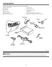
ASSEMBLY
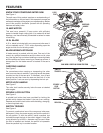
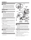
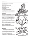
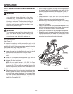
Follow the directions below for using the laser guide:
Removing Your Mark:
Position the laser line near the left edge of your mark on the
work surface in order to remove the mark.
To Cut Your Mark:
Position the laser line near or over your mark on the work
surface in order to cut the mark.
To Leave Your Mark:
Position the laser line near the right edge of your mark on
the work surface in order to leave the mark.
After you have become familiar with using the laser guide,
you will be able to remove, cut, or leave your mark on the
work surface. Practice will teach you the correct position for
aligning the laser line with your mark.
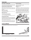
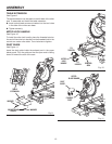
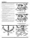
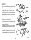
CUTTING A SLOT IN THE ZERO CLEARANCE
THROAT PLATE
In order to use your compound miter saw, you must cut
a slot through the zero clearance throat plate to allow for
blade clearance. To cut the slot, set your saw at 0
°
miter,
turn saw on and allow the blade to reach full speed, then
carefully make a straight cut as far as it will go through the
throat plate. Turn your saw off and allow the blade to come
to a complete stop before raising the saw arm.
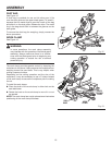
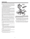
Next, adjust the bevel angle to 45
°
, turn your saw on and al-
low the blade to reach full speed, then carefully make another
cut through the zero clearance throat plate. The slot in the
throat plate will then be wide enough to allow the blade to
pass through it at any angle from 0
°
to 45
°
.
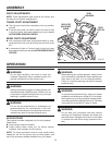
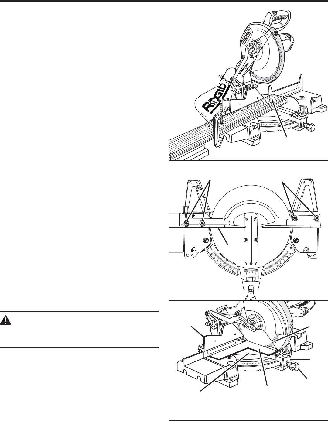
NOTE: Many of the illustrations in this manual show only
portions of your compound miter saw. This is intentional so
that we can clearly show points being made in the illustra-
tions. Never operate your saw without all guards securely
in place and in good operating condition.
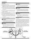
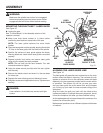
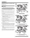
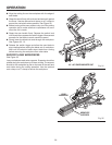
SQUARING THE SAW BLADE TO THE FENCE
See Figures 17 - 21
Unplug your saw.
WARNING:
Failure to unplug your saw could result in accidental
starting causing possible serious personal injury.
Remove the screws holding the throat plate in place.
Remove the throat plate.
Pull the saw arm all the way down and engage the lock
pin to hold the saw arm in transport position.
Loosen the miter lock handle approximately one-half
turn.
BROKEN
RED LINE
Fig. 18
VIEW OF BLADE SQUARE WITH FENCE
Fig. 17
FENCE
SOCKET HEAD
SCREW(S)
SOCKET HEAD
SCREW(S)
Fig. 16
1
5
2
0
2
5
3
0
3
5
4
0
4
5
1
0
1
4
SLIDING
MITER
FENCE
BLADE
MITER
LOCK
PLATE
MITER
LOCK
HANDLE
FRAMING
SQUARE
MITER
TABLE