


Page 22
2
7
8
910
11
12
13
14
15
0
0
1
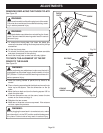
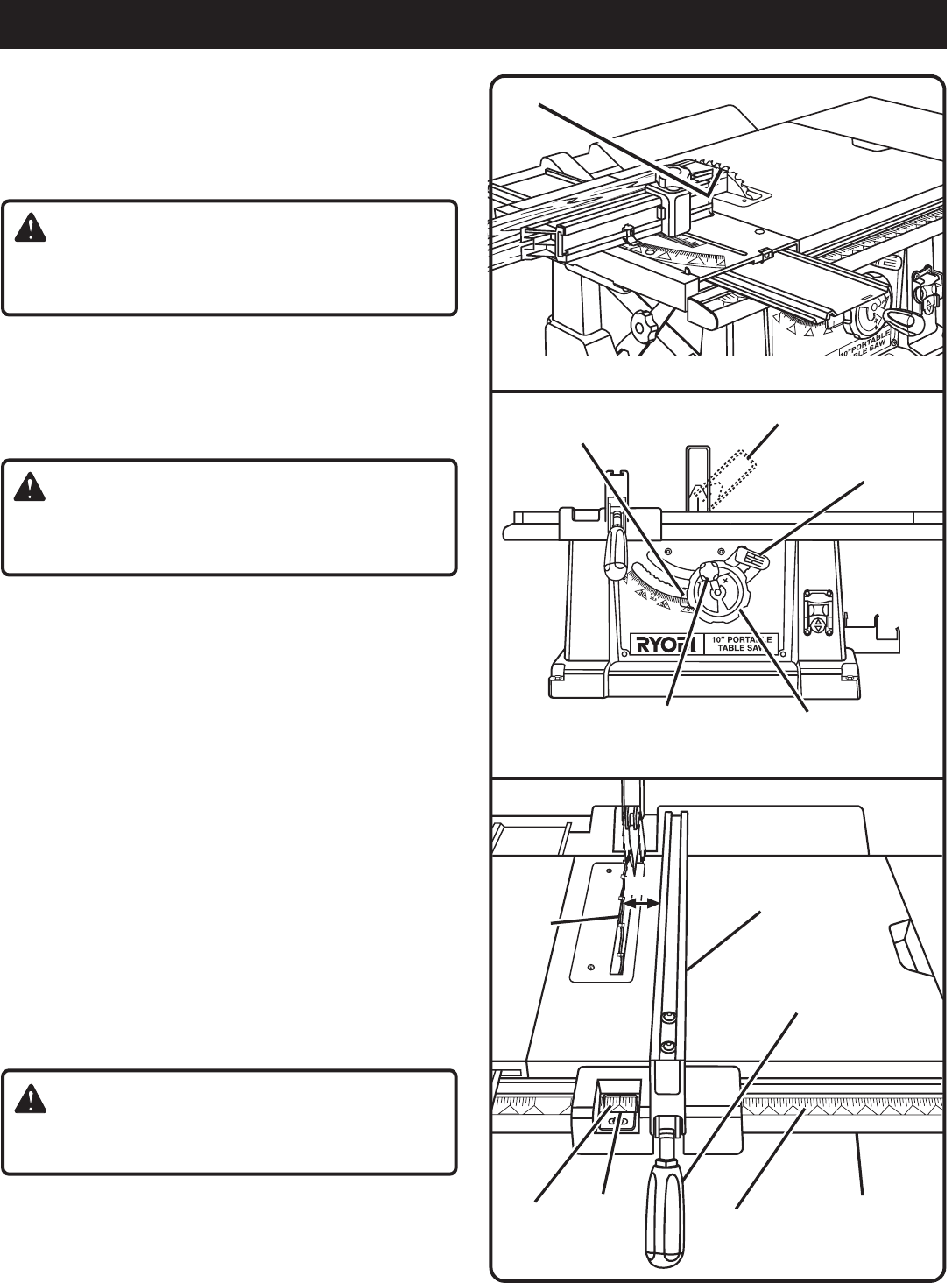
GULLET
Fig. 22
FRONT RAIL
Fig. 20
BEVEL
INDICATOR
BEVEL
LOCKING LEVER
BEVEL
HANDLE
Fig. 21
LOCKING
HANDLE
BLADE
RIP
FENCE
2 IN.
MARK
SCALE
SCALE
INDICATOR
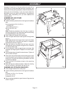
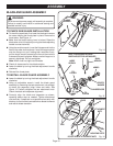
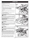
TO ADJUST THE BLADE DEPTH
The blade depth should be set so that the outer points of the
blade are higher than the workpiece by approximately 1/8 in.
to 1/4 in. but the lowest points (gullets) are below the top
surface.
See Figure 21.
WARNING:
Unplug the saw and make sure the blade guard assembly
is installed and working properly to avoid serious personal
injury.
Raise the blade by turning the blade adjusting handle
counterclockwise or lower it by turning the handle
clockwise.
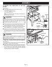
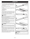
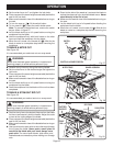
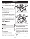
TO ADJUST THE BLADE ANGLE
See Figure 22.
WARNING:
Unplug the saw and make sure the blade guard assembly
is installed and working properly to avoid serious personal
injury.
Unlock the bevel locking lever.
Angle the blade by turning the bevel handle until the bevel
indicator shows the correct angle.
Lock the bevel locking lever securely while holding the
bevel handle in place.
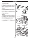
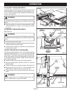
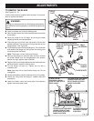
TO SET THE SCALE TO THE BLADE
The scale is usable from 5/8 in.-20 in. (16 mm-686 mm) to the
right side of the blade and 0-7 in. (0-178 mm) on the left side
of the blade. The operator can select any desired dimension
within those ranges. Use the following steps to set the scale
to the blade and scale indicator. Begin with the blade at a
zero angle (straight up).
Loosen the rip fence by raising the locking handle.
Using a framing square, set the rip fence 2 in. from the
blade tip edge.
Loosen the screw on the scale indicator.
See Figure 23.
Adjust the front rail until the 2 in. mark is placed at the
scale indicator. Align the rear rail to the front rail.
Tighten the screw and check the dimension and the rip
fence.
WARNING:
Blades coast after turn off. Possible serious injury can
occur if hands come in contact with blade.
ANGLED BLADE
OPERATION
BLADE
ADJUSTING
HANDLE
45º Adjustment
0º Adjustment
2 in.