


Page 35
ADJUSTMENTS
WARNING:
Begin by unplugging your saw. Failure to unplug saw
could result in accidental starting causing possible serious
injury.
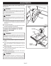
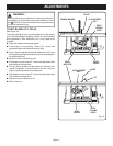
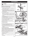
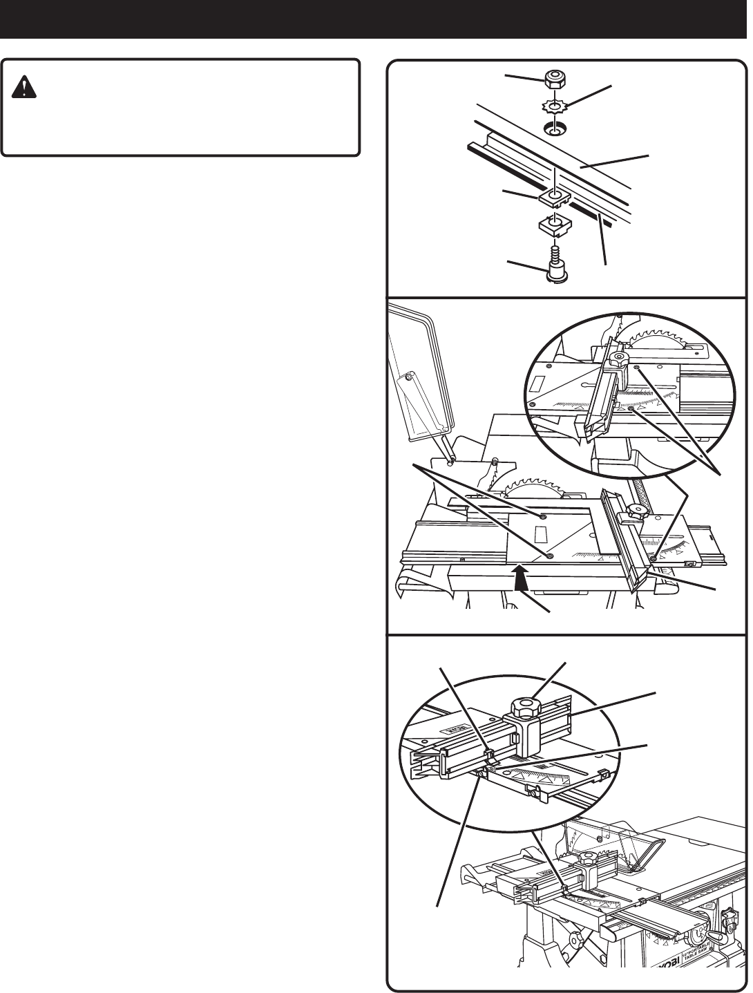
TO ADJUST THE MITER FENCE
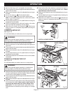
Set the miter fence (H) at 0° as shown in figure 46. Miter
indicator (I) should be set precisely on 0° and secured in
place with adjusting clamp (F).
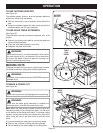
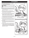
There are four slides located under the sliding miter table.
These slides let the miter table move on the base. Three
slides are mounted on eccentric screws that can be
adjusted by loosening the hex nuts on top of the miter
table.
See Figure 45.
Loosen the rear hex nuts (K) on top of sliding miter table
for this adjustment procedure.
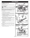
Note: The front screws are only needed to remove
excessive play in the slides due to wear from extended
use. They are not needed for this procedure. The right
front hex nut is a non-eccentric pivot and should never be
loosened.
Adjust the right rear eccentric screw from the lower side
of the miter table so that maximum play exists between
the slide and miter base.
Push left rear of miter table snugly against miter base as
shown by the arrow (M) in figure 46 and secure.
Place a framing square firmly against the miter fence, with
the other side against the blade.
Adjust left rear screw from underneath miter table until
miter fence and blade are square with each other.
Tighten hex nut securely.
Adjust right rear screw from underneath miter table to
remove excessive play.
Tighten hex nut securely.
Recheck your setups carefully. Also make sure all screws,
hex nuts, etc. have been tightened securely.
If sliding miter table assembly is still not square with the
blade, repeat the above procedures as needed.
Make sure that slides remain square to miter base edge
to prevent “cocking” which will result in excessive play in
miter table.
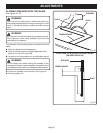
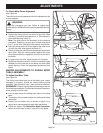
TO ADJUST QUICK-STOP
The quick-stop is preset at the factory to stop the miter fence
at exactly 0°. However, when sliding miter table adjustments
are made, these adjustments may cause the quick stop to
need adjusting. Check quick-stop with miter scale set at 0°.
If adjustments are needed, proceed with the following steps:
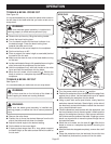
Loosen the eccentric screw holding the quick-stop.
Place the quick-stop against the miter fence with miter
scale set at 0°.
See Figure 47.
Adjust eccentric screw until it holds quick-stop securely
against miter fence.
Retighten hex nut, securing eccentric screw and quick-
stop.
Check your work. If the quick-stop is not at 0°, repeat
above steps.
Fig. 45
Fig. 46
K
H
Fig. 47
SLIDE
LIP OF BASE
ECCENTRIC
SCREW
K
M
ZERO
DEGREES
MITER FENCE
ADJUSTING
CLAMP
MITER INDICATOR
QUICK STOP AND
ECCENTRIC SCREW
HEX NUT
MITER
TABLE
STAR WASHER