


Page 11
ADJUSTMENTS
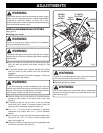
■ Release the plunge lock and release lever.
■ Grasp the handles and lower router until stop bar con-
tacts stop screw. Tighten the plunge lock and release
lever to lock the cutter at the desired depth of cut.
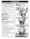
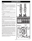
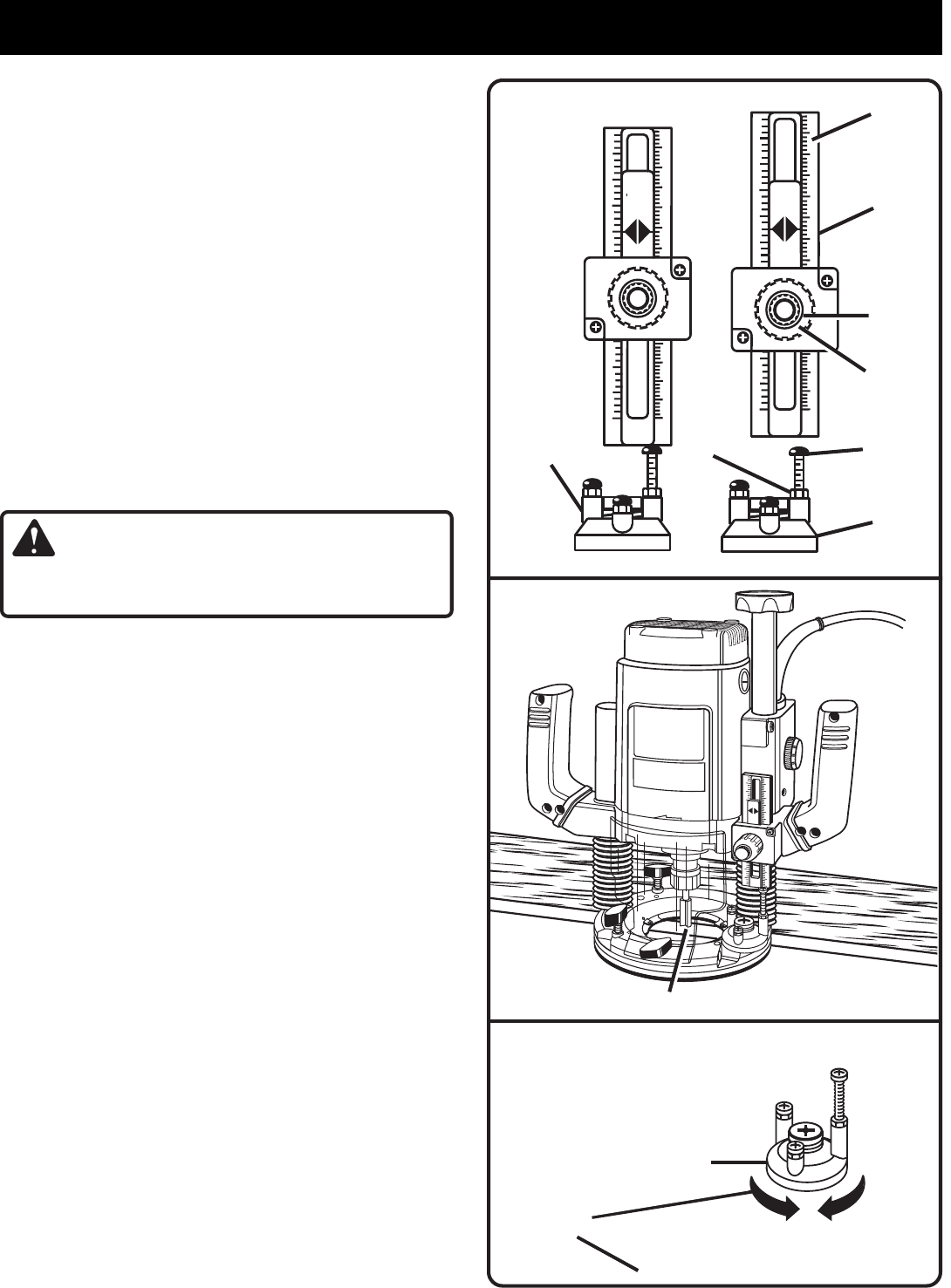
DEPTH STOP SYSTEM
See Figure 10.
The depth stop is located on the base of your router and
makes it possible to make deep or heavy cuts in successive
passes by use of preset depth of cut changes. Adjustable
stops are provided, making depth of cut changes quick and
easy. The depth stop, also known as a revolving turret,
rotates on a ball detent design in the router base.
A preset cutting depth is achieved by plunging router until stop
bar comes in contact with the stop screw on depth stop.
The adjustable stops have screws that may be adjusted
approximately 1/2 in. (13 mm).
TO SET DEPTH STOP SETTINGS
■ Unplug your router.
WARNING:
Failure to unplug your router could result in accidental
starting causing serious injury.
■ Loosen lock knob and turn adjustment knob clockwise,
raising stop bar to it's highest position.
■ Determine which adjustable stops will be used to reach
desired depth of cut.
■ The stop screw on each stop can be adjusted to the
desired height by loosening the hex nut with a 3/8 in.
(10 mm) open end wrench and turning it in or out with
your fingers. Secure stop screw in position by retight-
ening hex nut with wrench. Do not overtighten hex
nut. Set stops to desired heights, spreading the entire
depth of cut over the number of stops used.
■ Rotate depth stop until the highest depth stop is aligned
with the stop bar.
■ Raise cutter by releasing plunge lock and release lever.
■ Place router on a flat surface, and lower router until tip
of cutter barely touches flat surface.
■ Tighten plunge lock and release lever to lock cutter at
"zero" depth of cut.
■ Turn adjustment knob counterclockwise to lower stop
bar against stop, then tighten lock knob securely. The
highest stop now becomes "zero" depth of cut setting.
■ Release plunge lock and release lever and raise router.
Rotate depth stop so that next highest depth stop aligns
with stop bar. This locates cutter for the initial pass.
■ Tighten plunge lock and release lever, locking cutter at
desired depth of cut.
■ Rotate depth stop after each pass. Make as many suc-
cessive passes as needed to obtain desired depth of
cut, progressively lowering router to next depth of cut
setting with each pass.
Fig. 10
Fig. 9
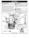
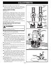
CUTTER EXTENDED BELOW SUBBASE
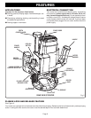
DEPTH STOP ROTATES FOR
DEPTH OF CUT CHANGES
Fig. 8
ROUTER BASE
DEPTH STOP
(TURRET)
in m
m
1
2
3
9
3
1
3
2
3
1
64
3
9
8
1
2
3
3
2
3
1
3
2
3
4
3
9
8
1
2
3
in cm
in cm
SCALE
ADJUSTABLE
STOP
DEPTH
STOP
(TURRET)
HEX NUT
ADJUSTMENT
KNOB
LOCK
KNOB
STOP
SCREW
STOP BAR