


Page 21
WARNING:
To ensure safety and reliability, all repairs—with the
exception of the externally accessible brushes—should
be performed by a Ryobi Factory or Authorized Service
Center.
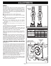
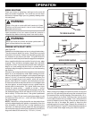
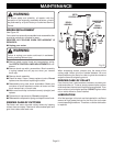
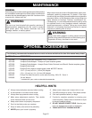
BRUSH REPLACEMENT
See Figure 25.
Your router has externally accessible brush assemblies that
should be periodically checked for wear.
PROCEED AS FOLLOWS WHEN REPLACEMENT IS
REQUIRED:
■ Unplug your router.
WARNING:
Failure to unplug your router could result in accidental
starting causing serious injury.
■ Remove depth control knob and compression spring.
See DEPTH CONTROL KNOB ADJUSTMENTS for ref-
erence.
■ Remove brush cap with a screwdriver. Brush assembly
is spring loaded and will pop out when you remove
brush cap.
■ Remove brush assembly.
■ Check for wear. If worn, always replace in pairs. Do not
replace one side without replacing the other.
■ Reassemble using new brush assemblies. Make sure
curvature of brush matches curvature of motor and that
brush moves freely in brush tube.
■ Make sure brush cap is oriented correctly (straight) and
replace.
■ Tighten brush cap securely. Do not overtighten.
■ Reassemble compression spring and depth control knob.
PROPER CARE OF CUTTERS
Get faster and more accurate cutting results by keeping
cutters clean and sharp. Remove all accumulated pitch and
gum from cutters after each use.
When sharpening cutters, sharpen only the inside of the
cutting edge. Never grind the outside diameter. Be sure
when sharpening the end of a cutter to grind the clearance
angle the same as originally ground.
PROPER CARE OF COLLET
From time to time, it also becomes necessary to clean your
collet and collet nut. To do so, simply remove collet nut from
collet and clean the dust and chips that have collected. Then
return collet nut to its original position. DO NOT tighten collet
nut on collet without a cutter installed.
LUBRICATION
All of the bearings in this tool are lubricated with a sufficient
amount of high grade lubricant for the life of the unit under
normal operating conditions. Therefore, no further lubrication
is required.
MAINTENANCE
Fig. 25
BRUSH
CAP
BRUSH
ASSEMBLY
BRUSH
CAP
DEPTH
CONTROL KNOB
BRUSH
ASSEMBLY
COMPRESSION
SPRING
in mm
1
2
3
9
3
1