


Page 10
ADJUSTMENTS
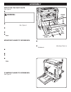
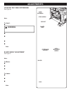
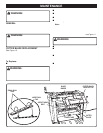
LEVELING THE TABLE EXTENSIONS
See Figure 6.
The infeed and outfeed table extensions are attached to
the planer. Shipped in a folded, "upright" position, the
table extensions must be in the "down" position before
planing can begin. For accurate planing, table exten-
sions must be level with the planer table.
Note: For optimum performance, always check to make
sure the table extensions are level before beginning
planing operations.
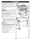
To Level:
■ Unplug your planer.
WARNING:
Failure to unplug your planer could result in accidental
starting causing possible serious personal injury.
■ Place a straight edge or level across both the planer
table and table extensions.
■ If adjustment is necessary, lift table extensions and
loosen lock nuts. Adjust stop screws (one on each side)
until extension table is level with planer table.
■ Press down on the table extension to ensure the table
extension is properly seated.
■ Tighten lock nuts securely when adjustments are com-
plete.
Note: Four screws attach table extensions to support
bars; loosening these screws may aid in leveling
table extensions.
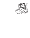
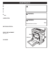
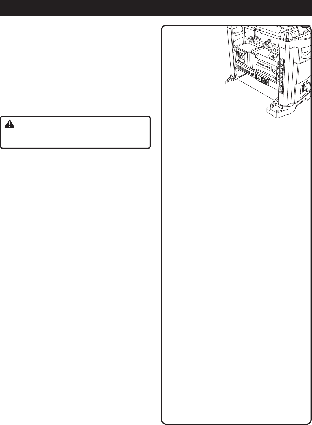
BLADE HEIGHT ADJUSTMENT
See Figure 7.
Raising and lowering the depth adjustment handle controls
the depth of cut on your planer.
Note: Never adjust blade height with cutter lock in the
"locked" position (pushed to the far right).
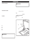
To Raise:
■ Push cutter lock to the left to unlock cutter head
assembly.
■ Turn the depth adjustment handle clockwise to desired
height.
■ Once cutter head is in desired position, lock cutter head
assembly in place by pushing cutter lock handle to the
right.
To Lower:
■ Push cutter lock to the left to unlock cutter head
assembly.
■ Turn the depth adjustment handle counterclockwise to
desired height.
■ Once cutter head assembly is in the desired position,
lock cutter head in place by pushing cutter lock handle
to the right.
Note: Each complete rotation of the handle moves the
cutter head assembly 5/64 in. (2 mm).
Fig. 6
Fig. 7
LOCK NUT
STOP SCREWS
TABLE
EXTENSION
PLANER
TABLE
LOCK
CUTTER HEAD
ASSEMBLY
DEPTH
ADJUSTMENT
HANDLE
UNLOCK
1-3/4
1-1/2
1-1/4
1/4
0