


Page 12
ADJUSTMENTS
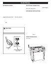
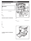
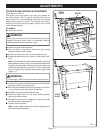
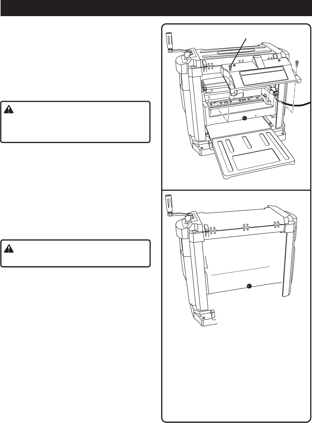
CUTTER BLADE SIDEWAYS ADJUSTMENT
See Figures 10 and 11.
During the use of your planer, tiny nicks may appear on
the cutter blades. This is a result of picking up sand or
other particles on the workpiece and then running the
workpiece through the planer. To eliminate any imper-
fections during the planing process, adjust one or both
cutter blades laterally.
To Adjust:
■ Unplug your planer.
WARNING:
Failure to turn the planer off, remove the switch key, and
unplug the planer could result in accidental starting
causing possible serious personal injury.
■ Lower the cutter head assembly.
■ From the back of the planer, remove the two screws
holding the dust chute in place.
■ Remove the dust chute then lift off the safety cover.
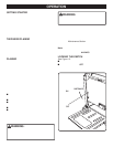
■ Rotate the cutter block until it locks in place (every 180°
turn).
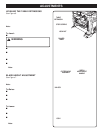
Note: From beneath the cutter head assembly, using the
planer table as a mirror, touch the threaded spindle where
it meets the planer table. Carefully move your fingers up
toward the drive belt until you touch it. Turn the drive belt
with your fingers until the cutter head locks in place
(see
Figure 11.)
WARNING:
To avoid injury, NEVER rotate the cutter block by hand.
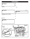
■ Loosen the socket head bolts holding the blade binder
and cutter blade to the cutter block.
■ Move the cutter blade to the left or right side up to 3/64 in.
(1 mm) laterally using a flat head screwdriver.
■ Retighten the socket head bolts securely.
■ Place the safety cover on the cutter head assembly
leaving the screws loose.
■ Reinstall the dust chute by slipping it under the screws
and lock washers (see page 9).
■ Tighten screws securely.
Note: Cutter blades require only slight adjustments to
offset planing imperfections.
Fig. 10
Fig. 11
SAFETY
COVER
CUTTER
BLOCK
SCREWS
CUTTER
BLOCK
BLADE
BINDER