


Page 15
WARNING:
When servicing, use only identical Ryobi replacement
parts. Use of any other part may create a hazard or cause
product damage.
GENERAL
Avoid using solvents when cleaning plastic parts. Most
plastics are susceptible to damage from various types of
commercial solvents and may be damaged by their use. Use
clean cloths to remove dirt, carbon dust, etc.
WARNING:
Do not at any time let brake fluids, gasoline, petroleum-
based products, penetrating oils, etc. come in contact
with plastic parts. They contain chemicals that can
damage, weaken or destroy plastic.
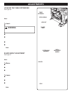
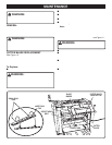
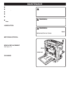
CUTTER BLADE REPLACEMENT
See Figure 15.
Your planer is equipped with two double-edged cutter
blades attached to a rotating cutter block. Worn cutter
blades will affect cutting accuracy and may produce ridges
on the workpiece.
To Replace:
■ Unplug your planer.
WARNING:
Failure to turn the planer off, remove the switch key, and
unplug the planer before servicing or making adjust-
ments could result in accidental starting causing possible
serious personal injury.
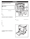
MAINTENANCE
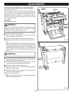
■ Lower the cutter head assembly.
■ From the back of the planer, remove the two socket
head screws holding the dust chute in place.
■ Remove the dust chute then lift off the safety cover.
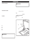
■ If necessary, rotate the cutter block until it locks in place
(every 180° turn the cutter block will lock).
Note: Rotating the cutter block is accomplished from
beneath the cutter head assembly. Using the planer table
as a mirror, touch the threaded spindle where it attaches
to the planer table. Carefully move your fingers up until
you touch the drive belt. Turn the drive belt with your
fingers until the cutter head locks in place (
see Figure 11
).
WARNING:
To avoid injury, never rotate the cutter block by hand.
■ Carefully remove the socket head bolts.
■ Place your thumb and index finger on the finger tabs and
carefully lift the blade binder and cutter blade off the cutter
block.
■ Lightly oil new cutter blade. Align the cutter blade on the
underside of the blade binder placing the cutter blade
(sloped edge against the blade binder) in the small oval
tabs.
■ Place blade binder with cutter blades on the cutter block
in the large oval tabs and aligning with the six socket head
bolt holes.
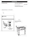
Fig. 15
CUTTER BLOCK
LOCK BUTTON
FINGER TABS
SOCKET HEAD
BOLT
BLADE
BINDER
CUTTER
BLADE
LARGE OVAL
TAB
SMALL OVAL
TABS