


Page 9
ASSEMBLY
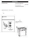
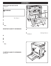
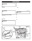
INSTALLING THE DUST CHUTE
See Figure 4.
■ Unplug your planer.
WARNING:
Failure to turn the planer off, remove the switch key, and
unplug the planer before servicing or making adjustments
could result in accidental starting causing possible
serious personal injury.
■ From the back of the machine, locate the two screws on
the cutter head assembly.
See Figure 4.
Turning coun-
terclockwise, loosen each screw.
■ Slide the dust chute between the lock washer and the
cutter head assembly, resting the dust chute on the
rubber bumper.
■ Insert the two dust chute knobs, turning clockwise.
■ Securely tighten the screws and dust chute knobs.
Note: To minimize sawdust accumulation on your
workpiece, attach either a 2-1/2 in. (64 mm) or 4 in.
(102 mm) shop vac hose to the end of the dust chute.
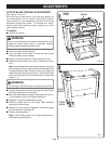
MOUNTING PLANER TO WORKBENCH
If your planer is to be used in a permanent location, it is
recommended you secure it to a workbench or other stable
surface. When mounting the planer to a workbench, holes
should be drilled through the supporting surface of the
workbench.
■ Mark holes on workbench where planer is to be mounted
using holes in planer base as a template for hole
pattern.
■ Drill four holes through workbench.
■ Place planer on workbench aligning holes in the planer
base with holes drilled in the workbench.
■ Insert four bolts (not included) and tighten securely with
lock washers and hex nuts (not included).
Note: All bolts should be inserted from the top. Install
the lock washers and hex nuts from the underside of the
workbench.
Supporting surface where planer is mounted should be
examined carefully after mounting to insure that no move-
ment during use can result. If any tipping or walking is
noted, secure workbench or support surface before begin-
ning planing operation.
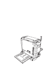
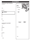
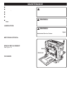
CLAMPING PLANER TO WORKBENCH
See Figure 5.
If the planer is to be used as a portable tool, it is recom-
mended you fasten it permanently to a mounting board that
can easily be clamped to a workbench or other stable
surface. The mounting board should be of sufficient size to
avoid tipping while planer is in use. Any good grade ply-
wood or chipboard with a 3/4 in. (19 mm) thickness is
recommended.
Fig. 5
Fig. 4
■ Mark holes on board where planer is to be mounted
using holes in planer base as a template for hole
pattern.
■ Follow last three steps in section
Mounting Planer to
Workbench.
If lag bolts are used, make sure they are long enough to go
through holes in planer base and material the planer is
being mounted to. If machine bolts are used, make sure
bolts are long enough to go through holes in planer base,
the material being mounted to, and the lock washers and
hex nuts.
SCREWS
DUST
CHUTE
DUST CHUTE
KNOBS