


Page 11
0
30
15
ADJUSTMENTS
WARNING:
To prevent accidental starting that could cause possible
serious personal injury, turn off the saw and unplug the
saw from the power source before making any
adjustments.
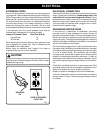
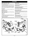
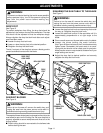
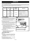
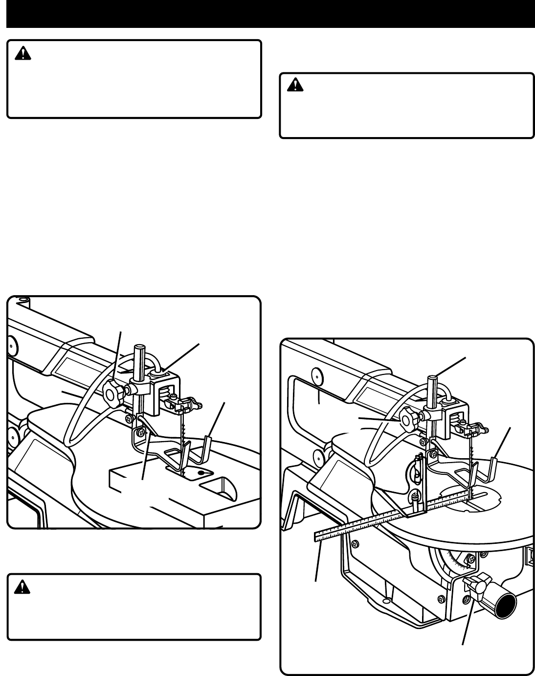
DROP FOOT
See Figure 6.
To prevent workpiece from lifting, the drop foot should be
adjusted so it just rests on the top of the workpiece. The drop
foot should not be adjusted so that the workpiece drags.
Always retighten the drop foot lock knob after each adjust-
ment has been made.
■ Loosen the drop foot lock knob.
■ Lower or raise the drop foot to the desired position.
■ Retighten the drop foot lock knob.
The tall, front part of the drop foot acts as a blade guard to
prevent accidental contact with the blade.
SAWDUST BLOWER
See Figure 6.
WARNING:
Failure to turn the saw off, remove the switch key, and
unplug the saw from the power source could result in
accidental starting causing possible serious injury.
The sawdust blower is designed and preset to direct air to the
most effective point on the cutting line. Be sure drop foot is
properly adjusted to secure workpiece and direct air to the
cutting surface.
■ Plastic tubing should be connected to the bellows tube
before starting the saw.
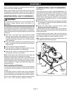
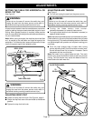
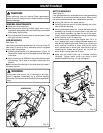
SQUARING THE SAW TABLE TO THE BLADE
See Figure 7.
WARNING:
Failure to turn the saw off, remove the switch key, and
unplug the saw from the power source could result in
accidental starting causing possible serious injury.
■ Loosen the drop foot lock knob and move drop foot rod all
the way up. Retighten drop foot lock knob.
■ Loosen the table lock knob to tilt the saw table until it is
approximately perpendicular or at right angle to the
blade.
■ Place a small square on the saw table next to the blade.
■ Loosen the screw holding the scale indicator.
See Figure 8.
Move indicator to the 0° mark and securely
tighten screw. Remember, the bevel scale is a conve-
nient guide but should not be relied upon for precision.
Make practice cuts on scrap material to determine if your
angle settings are correct.
■ Adjust the drop foot to desired position and securely
retighten the drop foot lock knob.
Fig. 7
DROP
FOOT
SMALL
COMBINATION
SQUARE
DROP FOOT ROD
TABLE LOCK KNOB
DROP
FOOT
DROP FOOT
LOCK KNOB
BELLOWS TUBE
PLASTIC
TUBING
DROP FOOT
LOCK KNOB
SAWDUST
BLOWER
Fig. 6