


18
OPERATION
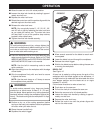
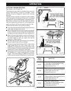
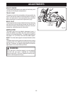
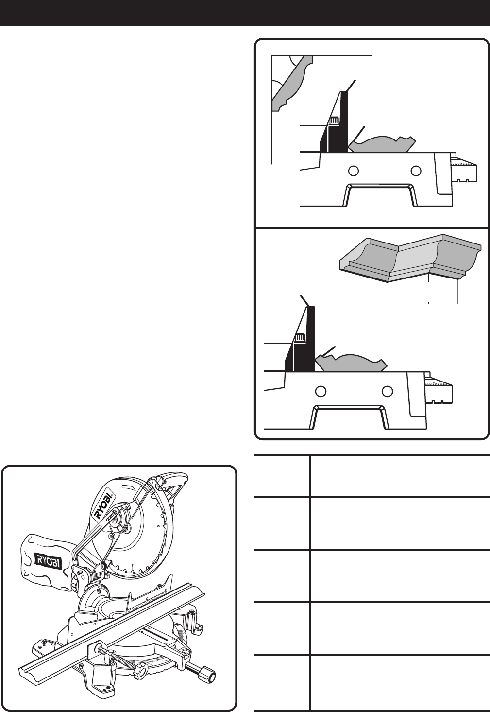
CUTTING CROWN MOLDING
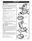
See Figures 14a, 14b, and 14c.
The compound miter saw is an excellent tool choice for
cutting crown molding. In order to fit properly, crown
molding must be compound mitered with extreme
accuracy.
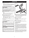
The two contact surfaces on a piece of crown molding
that fit flat against the ceiling and the wall of a room are
at angles that, when added together, equal exactly 90°.
Most crown molding has a top rear angle (the section
that fits flat against the ceiling) of 52° and a bottom rear
angle (the section that fits flat against the wall) of 38°.
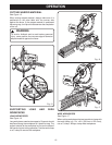
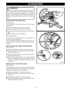
Follow these tips when cutting crown molding.
■ Lay the molding with its broad back surface flat on the
miter table and against the fence.
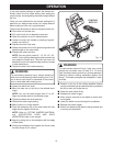
■ When setting the bevel and miter angles for compound
miters, remember that the settings are interdependent;
changing one angle changes the other angle as well.
■ Keep in mind that the angles for crown moldings are
very precise and difficult to set. Since it is very easy
for these angles to shift, you should first test all
settings on scrap molding.
■ Most walls do not have angles of exactly 90°; therefore,
you will need to fine tune your settings.
■ The bevel angle should be set at 33.85° and the miter
angle should be set at 31.62° either right or left,
depending on the desired cut for the application. See
the chart below for correct angle settings and correct
positioning of crown molding on miter table.
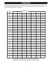
■ The settings in the chart below can be used for cutting
All Standard (U.S.) crown molding with 52° and 38°
angles. The crown molding is placed flat on the miter
table using the compound features of your miter saw.
Bevel
Angle Type of Cut
Setting
Left side, inside corner
1. Top edge of molding against fence
2. Miter table set right 31.62°
3. Save left end of cut
Right side, inside corner
1. Bottom edge of molding against fence
2. Miter table set left 31.62°
3. Save left end of cut
Left side, outside corner
1. Bottom edge of molding against fence
2. Miter table set left 31.62°
3. Save right end of cut
Right side, outside corner
1. Top edge of molding against fence
2. Miter table set right 31.62°
3. Save right end of cut
33.85°
33.85°
33.85°
33.85°
Fig. 14c
Fig. 14b
CEILING
W
A
L
L
52°
38°
FENCE
TOP EDGE AGAINST FENCE =
LEFT SIDE, INSIDE CORNER
RIGHT SIDE, OUTSIDE CORNER
INSIDE
CORNER
BOTTOM EDGE AGAINST FENCE =
RIGHT SIDE, INSIDE CORNER
LEFT SIDE, OUTSIDE CORNER
FENCE
OUTSIDE
CORNER
Fig. 14a
30
15
30
4
5
1
2
3
4
5
6
7
8
9
1
0
1
2
1
2
1
2
1
2
1
2
1
2
1
2
1
2
1
2