


6
NEGATIVE GROUNDED SYSTEM
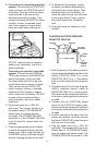
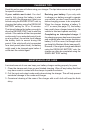
5. Connecting to a negative-grounded
system: Connect the red (POSITIVE)
output clamp to the POSITIVE post of
the battery. Rock and twist the clamp
back and forth to be sure a solid
electrical connection is made. Then
connect the black (NEGATIVE) output
clamp to a heavy, unpainted metal
part of the chassis or engine block,
away from the battery (see gure).
DO NOT connect clamp to negative
battery post, carburetor, fuel line or
sheet metal part.
Connecting to a positive-grounded
system: Connect the black (NEGA-
TIVE) output clamp to the NEGATIVE
post of the battery. Rock and twist
the clamp back and forth to be sure
a solid electrical connection is made.
Then connect the red (POSITIVE)
output clamp to a heavy, unpainted
metal part of the chassis or engine
block, away from the battery. DO NOT
connect clamp to positive battery
post, carburetor, fuel line or sheet
metal part.
6. Plug power cord into a 120V AC
wall outlet. The charger will be set to
the default state of 12V REGULAR
battery type, no charge rate (tes-
ter mode). The CONNECTED LED
should be lit. If the CONNECTED LED
is not lit, check for correct cable con-
nections.
7. Press the appropriate control buttons
to select the desired charge rate and
battery type. Within a few seconds, the
CHARGING (yellow) LED should light
and the charging process should start.
8. To disconnect the charger, unplug
its power cord before attempting to
disconnect the output clamps. Then,
standing away from the battery, re-
move the output clamp from the chas-
sis or engine block. Finally, remove
the output clamp from the battery
post.
9. Clean and store the charger in a dry
location.
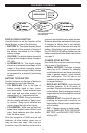
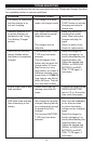
DIGITAL DISPLAY
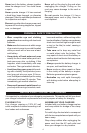
CHARGING BATTERY REMOVED
FROM THE VEHICLE:
NEGATIVE
BATTERY
CHARGER
BATTERY
24", 6 GAUGE CABLE
POWER
CORD
TO
GROUNDED
POWER
OUTLET
POSITIVE
1. Note the polarity of the battery posts by
checking the identication marks on the
battery: POSITIVE (POS, P or +) and
NEGATIVE (NEG, N or -). The positive
post is usually larger than the negative
post.
2. Attach at least a 24-inch-long, 6-gauge
(AWG), insulated battery cable to
NEGATIVE (NEG, N or -) battery post.
Rock and twist the clamp back and forth
to be sure a solid electrical connection
is made.
3. Connect the red (POSITIVE) output
clamp to the POSITIVE battery post.
Rock and twist the clamp back and forth
to be sure a solid electrical connection
is made.
4. Position yourself as far away from the
battery as possible, and then connect
the black (NEGATIVE) output clamp to
the free end of the cable.
5. Plug the power cord into a 120V AC
wall outlet. The charger will be set to the
default state of 12V REGULAR battery
type, no charge rate (tester mode). The
CONNECTED LED should be lit. If the