


assembly
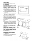
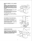
AUXILIARY MOUNTING FOR VERTICAL
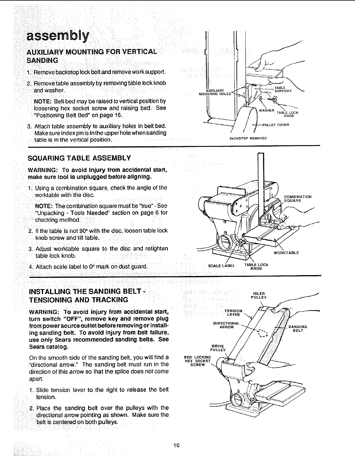
SANDING
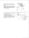
1. Remove backstoplock bolt and removework support.
2. Removetable assembly by removingtable lock knob
and washer.
NOTE: Beitbed may be raised to vertical position by
loosening he× socket screw and raising bed. See
"PositioningBelt Bed" on page 16.
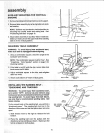
3. Attach table assembly to auxiliary holes in belt bed.
Make sure index pin is inthe upperhole when sanding
table is inthe vertical position.
AUXILIARY <
MOUNTING HOLES
J
f
BACKSTOP REMOVED
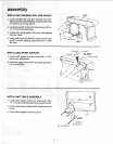
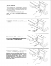
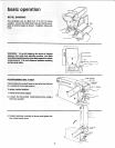
SQUARING TABLE ASSEMBLY
WARNING: To avoid tnjury from accidental start,
make sure tool Is unplugged before aligning.
1 Using a combination square, check the angle of the
worktable with the disc.
NOTE: The combination square must be "true"- See
"Unpacking - Tools Needed" section on page 6 for
checking method.
2. If the table is not 90° with the disc, loosen table lock
knob screw and tilt table.
3. Adjust worktable square to the disc and retighten
table lock knob.
4. Attach scale mabelto 0° mark on dust guard.
COMBINATION
SQUARE
SCALE LABEL TABLE LOCK
KNOB
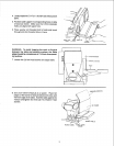
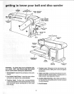
INSTALLING THE SANDING BELT -
TENSIONING AND TRACKING
WARNING: To avoid injury from accidental start,
turn switch "OFF", remove key and remove plug
{tom power source outlet before removing or install-
ing sanding belt. To avoid injury from belt failure,
use only Sears recommended sanding belts. See
Sears catalog.
On the smooth side of the sanding belt, you will find a
"directional arrow." The sanding belt must run in the
direction of this arrow so that the splice does not come
apart.
1. Slide tension lever to the right to release the belt
tension.
2. Place the sanding belt over the pulleys with the
directi0na arrow pointing as shown. Make sure the
: belt is Centered on both pulleys.
IDLER
PULLEY
TENSION
LEVER
DIRECTIONAL
ARROW BANDING
BELT
DRIVE
PULLEY
BED LOCKING
HEX SOCKE
SCREW
10