


4
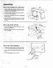
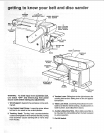
TENSION
LEVER
6
AUXILIARY
MOUNTING HOLE WORK SUPPORT
/ HEX SCREW
BED
3
TRACKING
KNOB
2
BED LOCKING
HEX SOCKET
HEAD SCREW
5
TABLE LOCK
KNOB
HOLE
1
WORK SUPPORT
SANDING
BELT
SANDING
PLATE
SANDING
DISC
/
WORKTABLE
ASSEMBLY
DISC
GUARD
7
ON-OFF MOUNTING
SWITCH HOLE
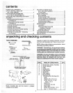
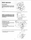
WARNING: To avold injury from accidental start,
turn switch "OFF" and remove plug from power
source outlet before making any adjustments.
1. Work Support. Supports the workpiece on the sand-
ing belt.
2. Hex Socket Head Screw. Loosening screw allows
belt bed to be raised to the vertical position.
3. Tracking Knob: Turning knob counterclockwise
causes sanding beit to move towardsthe disc;turning
knob €lockwise causes sanding belt to move away
from the disc. ....
/
4. Tension Lever. Slidinglever to the rightreleases the
sanding beit tension: sliding lever to the left applies
belt tension.
5. Table Lock Knob. Looseningknob allows the work-
table to be tilted for bevel sanding. (Scale pointer on
table trunnion; scale attached to base.)
6. Auxiliary Mounting Hole. Allowstable assembly to
be mounted for end sanding when the bed is placed
in vertical position.
7. On-Off Switch.
12