


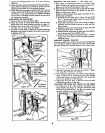

6. Retlghten all hex head scTew and _ntric bold-down
_rew. (Do not allow eccentric bushing to rotate when
ttlghtenlng.)
7. Correct adjustment existswhen there isno play between
the carriage and radial arm, and yet the carriage moves
freely. After adjustment is completed snugly tighten the
two adjusting set screws. Caution: Do not o_rtlghten.
8. Replace carriage cove_and lock knob ossernbly_
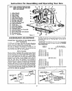
PROPEROPERATINGPROCEDURES
DRESS PROPERLY -- Operation of the saw is simple, safe
and easy-when properly done. Always be atert_ Do not
wear a tie or other loose artlcles. Keep long sleeves down
with cuffs fastened or wear short sleeves. NEVER STOP
BEING CAREFUL. One moment of inattention can cost you
a painful injury.
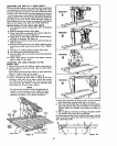
AVOID AWKWARD HAND POSITIONS-*Do not get
hands into a position in which a sudden slip can cause them
to move into the saw blade. NEVER OPERATE THE SAW
WITH THE ARMS IN A CROSSED POSITION. Never hold
work on right side of blade with left hand while pulling saw
with the right hand Do not attempt flee-hand cros_.cuttlngo
Use a push stickwhen hand gets too close to the blade in o
ripping position.
NEVER TWIST WORK --Twisting work will bind blade and
cause a kickback_
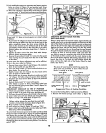
Safety Precaution
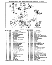
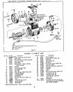
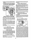
The motor is shipped with a shaft cap (Item 21,
figure 4) threaded onto the stub end of the motor
shaft_When this shaft end of the motor isnot being
used, this cap should always be in place.
LUBR|CATriON
Your saw isa fine machine and should be given the best of
care. If kept clean and properly lubricated, it will give many
years of trouble-free service° Before describing the various
points which may periodically require lubrication, IT 15
MORE IMPORTANT TO FIRST MENTION THE VARIOUS
SPOTS WHICH SHOULD NOT BE LUBRICATED°
NO LUBRICATION REQUIRED
Do not lubricate any ball races or any ball bearings.
Do not lubrTcate bearing fit of bevel index handle (Item 52,
figure 3) in yoke.
Do not lubricate the motor bearings° These are sealed ball
bearings and require no added lubrication.
Do not lubricate bevel latch pin (Item 31, figure 3) in yoke.
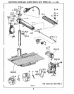
DO not lubricate between radial arm cap (Item 12, figure 1)
and radial arm_
PERIODICALLY LUBRICATE THESE POINTS
Use SAE No. 10-30 Auto Engine Oilo
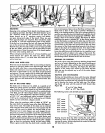
Apply a few drops of all along the swivel latch pin (item 6,
figure 3) only ff the pin has a tendency to stick.Remove the
left-hand carriage cover and use all sparingly to prevent it
from getting on the ball bearings or races.
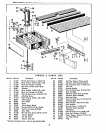
A light film of oil can be wiped on the face of the column
tube (Item 15, figure 1) and keyway to lubricate the fit
between this part and the key and column support (Items
21 and 19, figure 2).
Apply a few drops of all to the bearing surfaces of the
elevation crank shaft assembly (Item 29, figure 2). An othng
hole isprovided in the elevaffon shaft bearing bracket (Item
23, figure 2) to facilitate the lubrication of the rear bearing
support.
The thread on the elevation shaft assembly (Item 30, figure
2) can be lubricated through the oiling hole in the center
of the radial arm cap (Item 12, figure I).
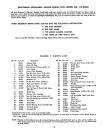
STANDARDSAW OPERATIONS
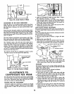
CROSS,CUI"rlNG
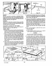
Crass-cuttlng isthe sawing of wood acrossthe grain. Planks
ore milled with the grain running the length of the plank_ If
a straight cross-cut is desired, the board is placed on the
saw table against the fence so that the grain is parallel to
the fence. See Figure 26.
NOTE
When cross-cuttlng normal pieces of lumber, the
long end of the board should be placed to the left
of the saw blade as the board isnormally held by
the left hand during operation_
The radial arm must be positioned at 0° as indicated by the
radial arm position indicator. The arm latch handle must be
indexed and tightened_ See page 11 "Angular Movement
and Lockingof the Radial Arm" far the mostaccurate setting
at the 0 ° index position. The yoke must be indexed at the 0 °
position, making the saw blade perpendicular to the rip
fence, and the yoke clamp handle placed in the locked pos_-
• .. o €IS
fion. The bevel index handle must be positioned at 0 ,
indicated by the bore| scale, and Iocked_Turn the elevation
crank to lower the saw until the btade teeth are approxl-
mately 1/32" below the table surface in the saw slot
made when performing the "PREI.IMINARY CROSS-CUT
AT THE 0 ° POSITION". Push the saw carriage to the rear
of the radial arm so the blade is behind the rip fence. Adjust
the saw guard sothe bottom is parallel to the table and set
the antl-klckback pawl assembly so it iust clears the board
to be cut. Turn the switch key "On" to start the saw motor.
Hold the board firmly against the rip fence with the left hand
and grasp the bevel index handle with the right hand. The
cut is then made by pulling the carriage forward until the
13