


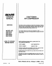
THIS MANUAL IS DESIGNED
TO MAKE IT AS EASY AS POSSIBLE
FOR YOU TO SET UP, OPERATE AND MAINTAIN
YOUR NEW CRAFTSMAN AIR COMPRESSOR
GENERAL INFORMATION
ASSEMBLYINSTRUCTIONS
You have purchased an air compressor outfit consisting
of a 2 cylinder single stage air compressor pump with air
tank, an air hose assembly, wheels, a foot extension
bracket and handle. You will also find an air chuck and a
helpful"Power Painting With Sprayers" booklet. This air
compressor can be either portable or permanently
mounted in one place.
Tools Needed For Assembly
TOols needed are: (1) a 9/16"socket or open end wrench
for attaching the wheels; and (2) a 7/16"socket or open
end wrench for attaching the foot extension bracket.
These units can be used for operating caulking guns,
grease guns, air brushes, sandblasters, air tools, etc., or
inflating tires and plastic toys, spraying weed killer, in-
secticides, etc.
'GENERAL DESCRIPTION OF OPERATION
To compress air, the pistons move up and down in the
Cylinder. On the downstroke, air is drawn in through the
air intake valve. The exhaust valve remains closed. On
the upstroke of the piston,air is compressed. The intake
valves close and compressed air is forced out through
the exhaust valve, through the check valve and into the
air tanK. Working air isnot available untilthe compressor
has raised the air tank pressure above that required at
Ithe air outlet. Since Ihe air tank pressure is usually
!greater than what is needed, the tank air is fed to the air
!outlet through a regulator. The air intake opening at the
=end of the console must be kept clear of obstructions
iwhich could reduce air detivery of the compressor.
Attaching Wheels, Handle, Etc.
i!
PROVID_ AD:OUAT =. CL:_.ARAN3-. STA-
BILJT_,"OR SUPPORT FOR o,,'u_:.,,,_'"'_ TH---
UNIT UP OR DOWN STAIR_ ANi_ F,T_=PS.
THE UNIT MUST B_ LIFTED OR PUSH--D UP
A RAMP.
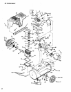
See diagram on page 10 for attaching wheels (40 or
40A), foot extension bracket (45) and handle (48). The
nuts and bolts can be found in a plastic bag which is
enclosed with the Owner's manuals, air hOSe,etc. Refer
to the illustration Page 10, Key No's. 28, 41, 42, 44, 46
and 47.
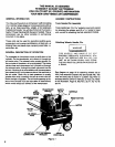
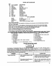
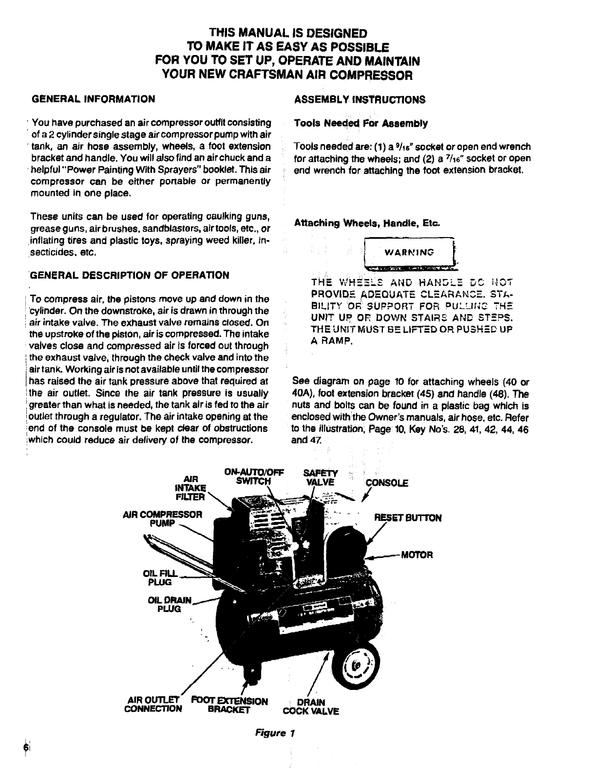
ON-AUTO/OFF
NR SWITCH
INTAKE
FILTER "_
AIR COMPRESSOR
PUMP
OIL
PLUG
PLUG
/
AIR OUll.E'T FOOTEXTENSION DRAIN
CONNECTION BRACKET COCK VALVE
Figure 1