


m
PR,=SSURE LOADS BEYOND DESIGN
LIMITS MAY CAUSE TANK RUPTUR- _ OR
-XFLOSIOi'.:. PRESSURE SWITCH OPERA-
TfON IS RELATED TO MOTOR HP, TANK
F_ATIN3 AF_D SAFETY VALVE SETTING. DO
NOT ATT__,,-IPT TO ADJUST REMOVE, OR
D-FEAT THE PRESSURE SWITCH.. OR
CHANGE At;D t_ODIFY ANY PRESSURE
CONTROL RELATED DEVICE.
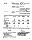
The pressure switch (19) starts the motor when the air
tank pressure drops below the factory set cut-in pres-
sure and stOpS the motor when the air tank pressure
reaches the factory set cut-off pressure. (See specifica-
tion chart, page 5.)
Safety Valve
WARNING
OVER-PRESSURIZATION OFTHE AIR TANK
MAY CAUSE TANK RUPTURE OR EXPLO-
SION. THE OUTFIT IS PROTECTED FROM
THE OVER-PRESSURIZATION BY A
SAFETY VALVE. DO NOT ELIMINATE, MAKE
ADJUSTMENTS OR SUBSTITUTIONS TO
THIS DEVICE.
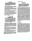
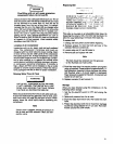
I Illll ,_' ",eAeEl't' VALVE_
ON-AUTOIOFF ., TANK PRESSURF
SWITCH
Immmm
m
m
AIR OUTLET
Figure 2
The pressure switch (19) is pre-set toshut off the motor
automatically at the maximum operating pressure. If the
)ressure switch does not shut off the outfit at its cul-off
_ressure seffJng, the safety valve will protect against
Jigh pressure by popping at its pre-set pressure.
Motor
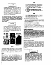
I:he motor has a thermal ovedoad prOtector.If the motor
_verheats for any reason, the overload protector will
;hut off the motor. The motor must be allowed to cool
_efore restarting. Turnthe ON-AUTO/OFF switch to the
)FF position. Depress the reset button Iocaled on the
_nd of the motor. To restart, turn the ON-AUTO/OFF
_itch to the ON position. Refer to Figure 1.
Note
If the overload protectorshuts the motor off fre-
quently, check for a possible voltage problem.
Low voltage can also be suspected when"
1. The motor does not get up to full power or
speed;
2. Fuses blOwout when starting the motor.
3. Lights dim and remain dim when motor is
started.
' i
.... Note
=
Avoid using long extension cords. They can
cause a power loss to the motor, Add extra air
hose instead of extension cords.
If an extension cord must be used:
- use only a 3-wire extension cord that has a 3-blade
grounding plug,and a 3-slot receptacle that willaccept
the plug on the product.
- make sure the cord is in good condition.
- the cord should bend longer than 50 feet.
- the minimum wire size is 12 gauge (AWG). (Wire size
increases as gauge number decreases. 10AWG and
8 AWG mayatso be used, 0o not use 14 AWG or 16
AWG,)
Pressure Release Valve
The pressure release valve located on the side of the
pressure switch is designed to unload air from the com-
pressor head automaUcally al unit shut off. This protects
the motor from starting against air pressure remaining in
the compressor head and tubing. When the motor stops
running, air will be heard escaping from the valve for a
few seconds. When the motor is running, no air should
be leaking from the pressure release valve.
MAINTENANCE
Replacing Air intake Filter
A dirty air intake filter will not allow the compressor to
operate at full capacity. When the intake filter becomes
dirty, oily,or covered with paint overspray, replace it. Do
not Operate the compressor with the air intake filter
removed. To replace the filter, use needle nosed pliers
and pull or pry the old filter out. Replace with new. Refer
to Figure 1.
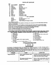
Checking Safety Valve
WARNING l_
OVER-PRESSURIZATL.qN CAUSING "I_ANK
RUPTURE OR EXPLOSION MAY OCCUR 1=
THE SAFETY' VALVE DO=S NOT WORK
PROPERLy. OCCASIONALLY PULL THE
RING ON THE SAF__TY VALVE TO MAKE
SURE THAT THE VALVE OPERATES
FRE£LY. IF THE VALVE IS STUCK OR DO_S
NOT OPERATE SMOOTHLY, IT MUST BE
REPLACED.