


RVmCEAND ADJUSTMENTS
i L ' lll'l..............
O
LH.
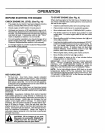
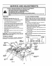
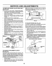
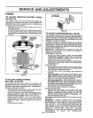
TO REPLACE MOWER BLADE DRIVE BELT
(See Fig. 23)
Park the tractor on level surface_ Engage parkingbrake,,
° Remove mowerdrivebelt(See'`TO REPLACEMOWER
DRIVE BELT _ inthis sectionof thismanual),
° Remove mower (See "TO REMOVE MOWER" inthis
section of this manual).
° Remove four screws from R°Homandrel cover and
remove cover. Unhook spring from bolt on mower
housing°
° Carefully roll belt off R.Homandrel pulley.,
° Remove belt from center mandrel pulley, idler pulley,
and LoHomandrel pulley,
° Remove any dirt or grass which may have accumu-
lated aroundmandrels and entire upper deck surface..
, Check secondary idler arm and idler to see that they
rotate freely,.
° Be sure spring is hooked in secondary idlerarm and
sway-bar bracket.
° Install new belt in lower groove of L,.Homandrel pulley,
idler pulley, and center mandrel pulley as shown°
= Roll belt over Ro.H,,mandrel pulley. Make sure belt isin
all grooves properly_
o Reconnect spring to bolt in mower housing and rein-
staleRoll° mandrel cover_
, Reinstall mower to tractor (See "INSTALL MOWER
AND DRIVE BELT" in the Assembly section of this
manual).
Reassemble mower drive belt (See '`TO REPLACE
MOWER DRIVE BELT" in this section of this manual).
CENTER
MANDREL
MANDREL
COVER
SECONDARY
IDLER ARM
MOWER BLADE
DRIVE BELT
SWAY-BAR IDLER
BRACKET PULLEY
FIG. 23
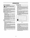
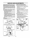
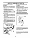
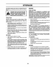
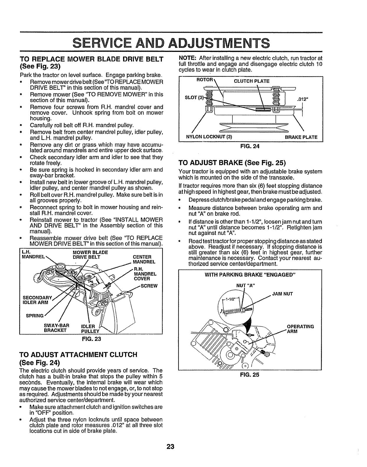
TO ADJUST ATTACHMENT CLUTCH
(See Fig. 24)
The electric clutch should provideyears of service, The
clutch has a built-in brake that stops the pulley within 5
seconds, Eventually, the internal brake wil! wear which
may cause the mower blades to notengage, or, to not stop
as required° Adjustments should be made byyour nearest
authorized service center/department.
° Make sure attachment clutch and ignition switches are
in "OFF" position°
° Adjust the three nylon locknuts until space between
clutch plate and rotor measures .012" at all three slot
locations cut in side of brake plate°
NOTE: After installinga new electric clutch, run tractor at
full throttle and engage and disengage electric clutch 10
cycles to wear inclutch plate,
NYLONLOCKNUT(3)
FIG. 24
BRAKE PLATE
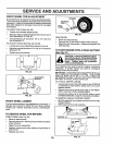
TO ADJUST BRAKE (See Fig. 25)
Your tractor is equippedwith an adjustable brake system
which is mountedon the side of the transaxle.
°
o
Iftractor requires more than six (6) feet stopping distance
at high speed inhighest gear, then brake must be adjusted,
• Depress clutch/brake pedaland engage parking brake°
Measure distance between brake operating arm and
nut "A" on brake rod.
If distance isother than 1-1/2", loosen jam nut and turn
nut "A" until distance becomes 1-1/2". Retighten jam
nut against nut "A"o
Road test tractor for proper stopping distance as stated
above. Readjust if necessary° If stopping distance is
still greater than six (6) feet in highest gear, further
maintenance is necessary. Contact your nearest au-
thorized service centeddepartmento
WITH PARKING BRAKE "ENGAGED"
NUT "A"
JAM NUT
OPERATING
ARM
FIG. 25
23