


AND ADJUSTMENTS
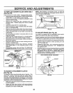
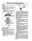
TO REPLACE MOTION DRIVE BELT
(See Fig. 26)
Park the tractoron level surface. Engage parking brake.
For ease ofservicethere isa beltinstallationguidedecal on
bottom of leftfootrest,
• Remove mower (See "TO REMOVE MOWER" in this
section of this manual..)
BELT REMOVAL -
° Engage parking brake (creates slack in belt).
° Remove belt from clutching and fan idler pulleys.
= Remove belt from transaxle pulley.
= Remove belt from engine pulley and front V-idler
pulley.
° Pull belt out of all belt keepers and remove from tractor.
BELT INSTALLATION -
= Place V part of belt into grooves on engine pulley and
front V-idler, making sure to route belt inside of all belt
keepers°
° Route belt on right side, coming from V-idler, towards
back of tractor, above midspan belt keeper and to top
of transaxle pulley.
° Route belt on left side, coming from engine pulley,
towards back of tractor and through loop in midspan
belt keeper.
• Place V part of belt into grooves on transaxle and fan
idler pulleys, making sure to route belt insideof all belt
keepers.
° Place belt around clutching idlers as shown, making
sure to route belt inside of all belt keepers.
° Check to be sure belt is positioned correctly and is on
proper side of all belt keepers_
° Reinstall mower°
IMPORTANT: CHECK BRAKE ADJUSTMENT..
TRACTOR V-BELT DRIVE SCHEMATIC
VIEWED FROM LH. SIDE OF TRACTOR
CLUTCHING TRANSAXLE
CLUTCHING IDLER BELT
FLAT
BELT
TWISTS
BELT
KEEPER
FAN
IDLER
ENGINE ABOVE BELT
PULLEY
V-IDLER KEEPER
AS VIEWED FROM BOTTOM
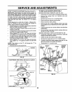
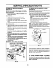
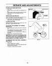
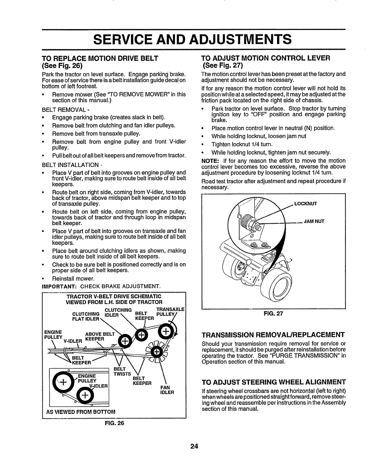
TO ADJUST MOTION CONTROL LEVER
(See Fig. 27)
The motion controllever' has been preset atthe factory and
adjustmentshould not be necessary.
If for any reason the motion controllever will not hold its
positionwhileat a selected speed, itmay be adjustedat the
friction packlocated on the rightside of chassis.
• Park tractor on level surface° Stop tractor by turning
ignition key to "OFF" position and engage parking
brake,
° Place motion control lever in neutral (N) position_
• While holding Iocknut,loosen jam nut
° Tighten Iocknut1/4 turn.
° While holdingIocknut, tightenjam nut securely.
NOTE: If for any reason the effort to move the motion
control Iever becomes too excessive, reverse the above
adjustment procedure by loosening locknutI/4 turn.
Road testtractor after'adjustment and repeat procedureif
necessary.
LOCKNUT
JAM NUT
FIG. 27
TRANSMISSION REMOVAL/REPLACEMENT
Should your transmission require removal for service or
replacement, it shouldbe purged after reinstaUationbefore
operating the tractor. See "PURGE TRANSMISSION" in
Operation section of this manual.
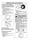
TO ADJUST STEERING WHEEL ALIGNMENT
tf steering wheel crossbarsare not horizontal (left to right)
when wheelsare positionedstra{ghtforward, removesteer-
ingwheel and reassemble per instructionsintheAssembly
section ofthis manual.
FIG. 26
24