


-27-
Model W1706 (Mfg. Since 8/10)
OPERATIONS
Operation Overview
The purpose of this overview is to provide the novice
machine operator with a basic understanding of how
the machine is used during operation, so the machine
controls/components discussed later in this manual are
easier to understand.
Due to the generic nature of this overview, it is not
intended to be an instructional guide. To learn more
about specific operations, read this entire manual and
seek additional training from experienced machine
operators, and do additional research outside of this
manual by reading "how-to" books, trade magazines, or
web sites.
To complete a typical operation, the operator does the
following:
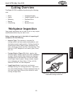
1. Examines the workpiece to make sure it is suitable
for cutting.
2. Adjusts the fence for the width of the cut and then
locks it in place.
3. Adjusts the table tilt, if necessary, to the correct
angle of the desired cut.
4. Loosens the guide post lock knob, adjusts the blade
guide height to between
1
⁄4" and 1" from the top
of the workpiece using the guide post elevation
handwheel, then tightens the guide post lock knob.
5. Checks to make sure the workpiece can safely pass
all the way through the blade without interference
from other objects.
6. Puts on safety glasses and a respirator.
7. Starts the dust collector and bandsaw, and waits for
the blade to come to full speed.
8. Holds the workpiece firmly and flatly against both
the table and fence, and then pushes the workpiece
into the blade at a steady and controlled rate until
the workpiece moves completely beyond the blade.
The operator is very careful to keep fingers away
from the blade and uses a push stick to feed narrow
workpieces.
9. Stops the bandsaw.
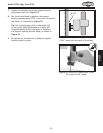
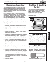
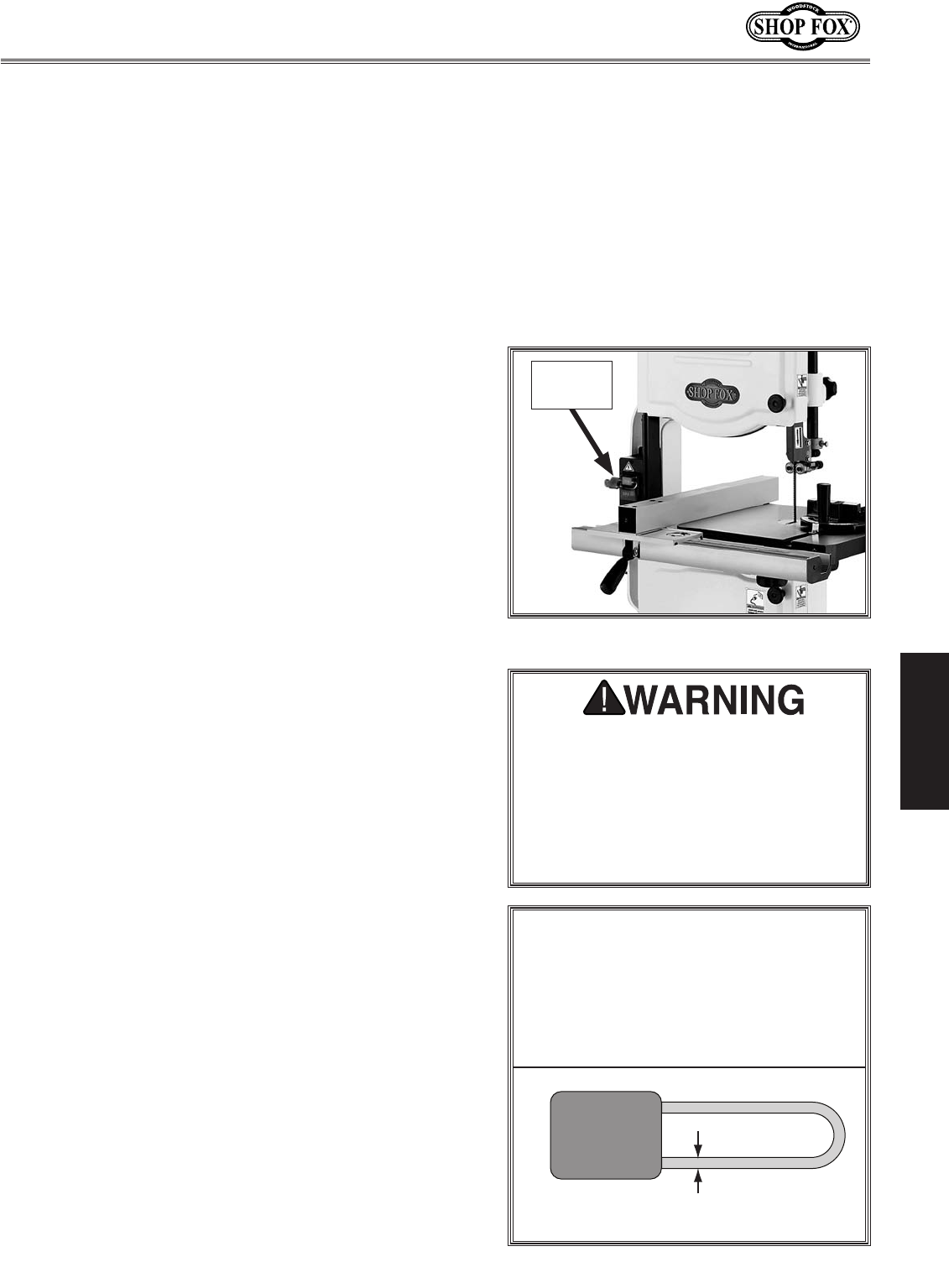
Disabling & Locking
Switch
The ON/OFF switch can be disabled and
locked with the provided padlock (see
Figure 34). While the padlock is inserted
through the ON button, the motor
cannot be started, which reduces the
risk of accidental startup by children of
unauthorized users.
Children or untrained people can
be killed or seriously injured by this
machine. If the machine is accessible to
children or other people, always disable
and lock the switch before leaving the
machine unattended. Place the key in a
well-hidden or secure location.
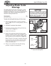
NOTICE
The switch can only be disabled if
the installed padlock shaft meets the
minimum diameter shown below;
otherwise, the shaft may be too small
to properly disable the switch.
Minimum Shaft Diameter = 0.192" – 0.2"
(4.8 – 5mm)
Figure 34. Padlock installed in the switch.
Padlock
Installed