


14.
Assembly and adjustments
To reduce the risk of injury, keep
p
ulley cover in place and in proper
w
orking order when operating.
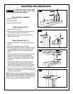
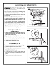
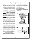
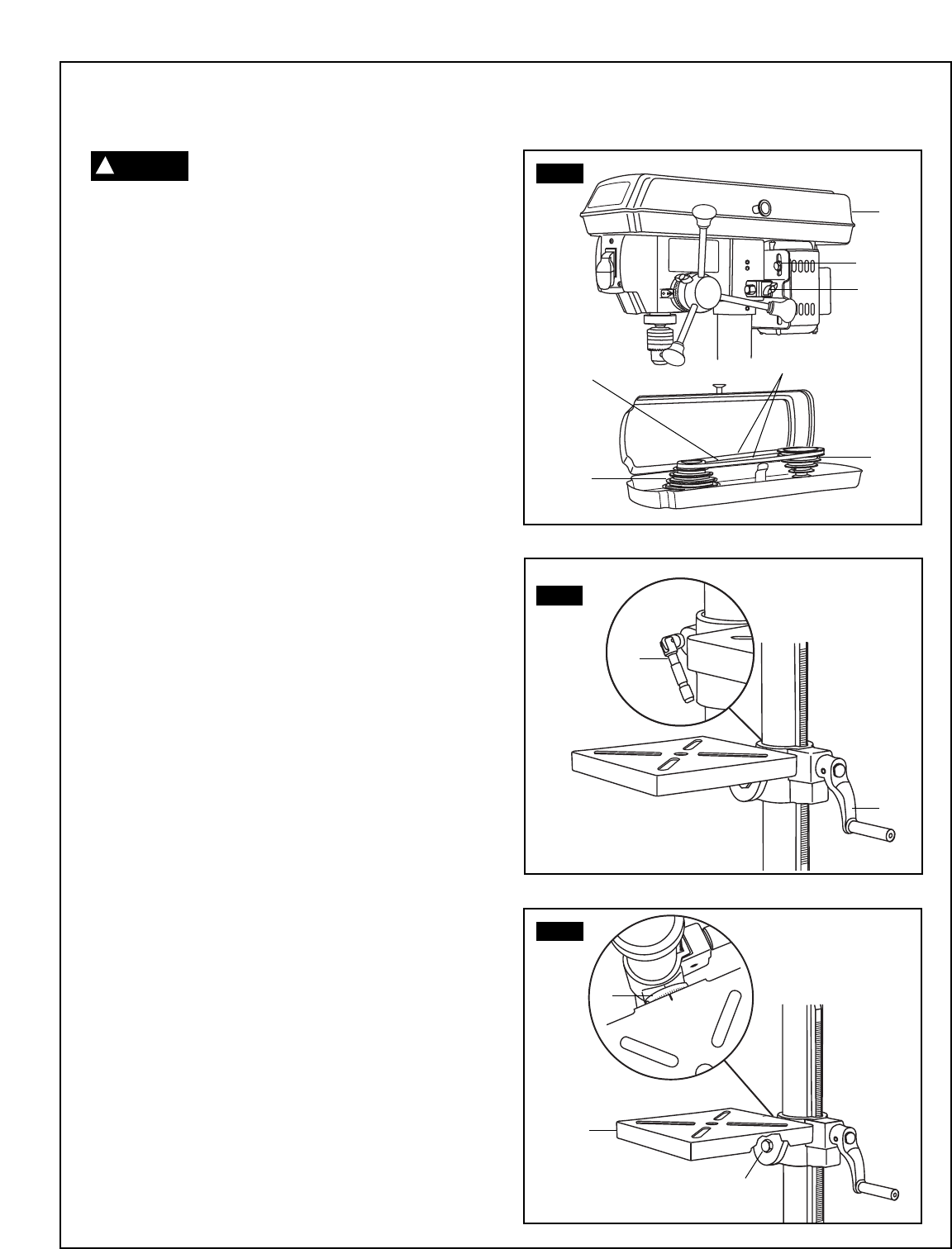
Adjust speeds and tension the belt (Fig. 17)
1. Open the drill press pulley cover (1).
2. Loosen the belt tension knobs (2) on both sides of the
drill press head.
3. Pull the motor (3) toward the drill press head.
4. Set the belt on the desired steps of the motor (4) and
spindle (5) pulleys according to the belt positions on the
spindle speed chart (Fig.
16).
5. Pull the motor away from the drill press head to
increase the belt tension. Tighten the tension ,knobs (2).
6. The belt (4) should be tight enough to prevent
slippage. Correct tension is set if the belt flexes about
1/2" (13 mm) when thumb pressure is applied at the
midpoint of the belt between the pulleys.
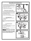
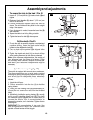
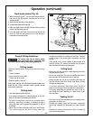
Table adjustments To raise
or lower (Fig. 18).
1. Raise or lower the table by loosening the column lock
handle
(1) and turning the crank handle (2) until the
table is at the desired height.
2. Tighten the table lock handle (1) before drilling.
3. Rotate the table around the column by loosening the
column lock handle (1) and turning the table around
the column to the desired position.
4. Tighten the lock handle before drilling.
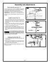
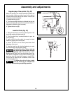
To tilt the table (Fig. 19)
The table can be tilted from 0 to 45° to the left and right.
1. Loosen the bevel lock bolt (1) with a wrench.
2. Tilt the table (2) to the desired angle, using the bevel
scale (3) as a basic guide.
3. Re-tighten the bevel lock bolt (1).
4. To return the table to its original position, loosen the
bevel lock bolt. Realign the bevel scale (3) to the 0°
setting.
5. Tighten the bevel lock bolt (1) with the wrench.
FIG. 17
4
1
3
2
5
6
1/2"
1
FIG. 18
1
2
0
1
0
°
1
0
°
2
0
°
2
0
°
3
0
°
3
0
°
4
0
°
4
0
°
FIG. 19
3
1
2
C
AUTION
!