


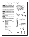
11.
Assembly and adjustments
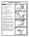
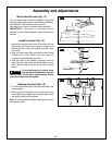
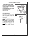
7. Insert the table support crank handle (9) into the worm
g
ear shaft on the side of the table support
(
8)
.
Make
sure the set screw (10) is aligned on the flat of the
shaft and as close to the table support as possible.
Tighten the set screw (Figure 7).
8. Position the table in the same direction as the base,
and tighten the column lock handle
(11).
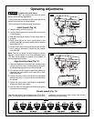
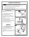
Drill press head to column (Fig. 8)
1. Lift the drill press head assembly (1) carefully and
place the mounting hole of the drill press head onto
the top of the column (2). Make sure the head is
seated properly on the column.
2. Align the direction of the drill press head to the
direction of the base and the table.
3. Tighten the two set screws
(3) using an Allen wrench.
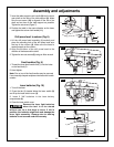
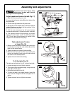
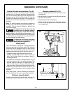
Feed handles (Fig. 9)
1. Thread the three feed handle rods (1) into the holes
on the feed hub (2).
2. Hand tighten.
Note: One or two of the feed handles may be removed
if an unusually-shaped workpiece interferes with handle
rotation.
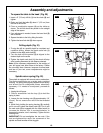
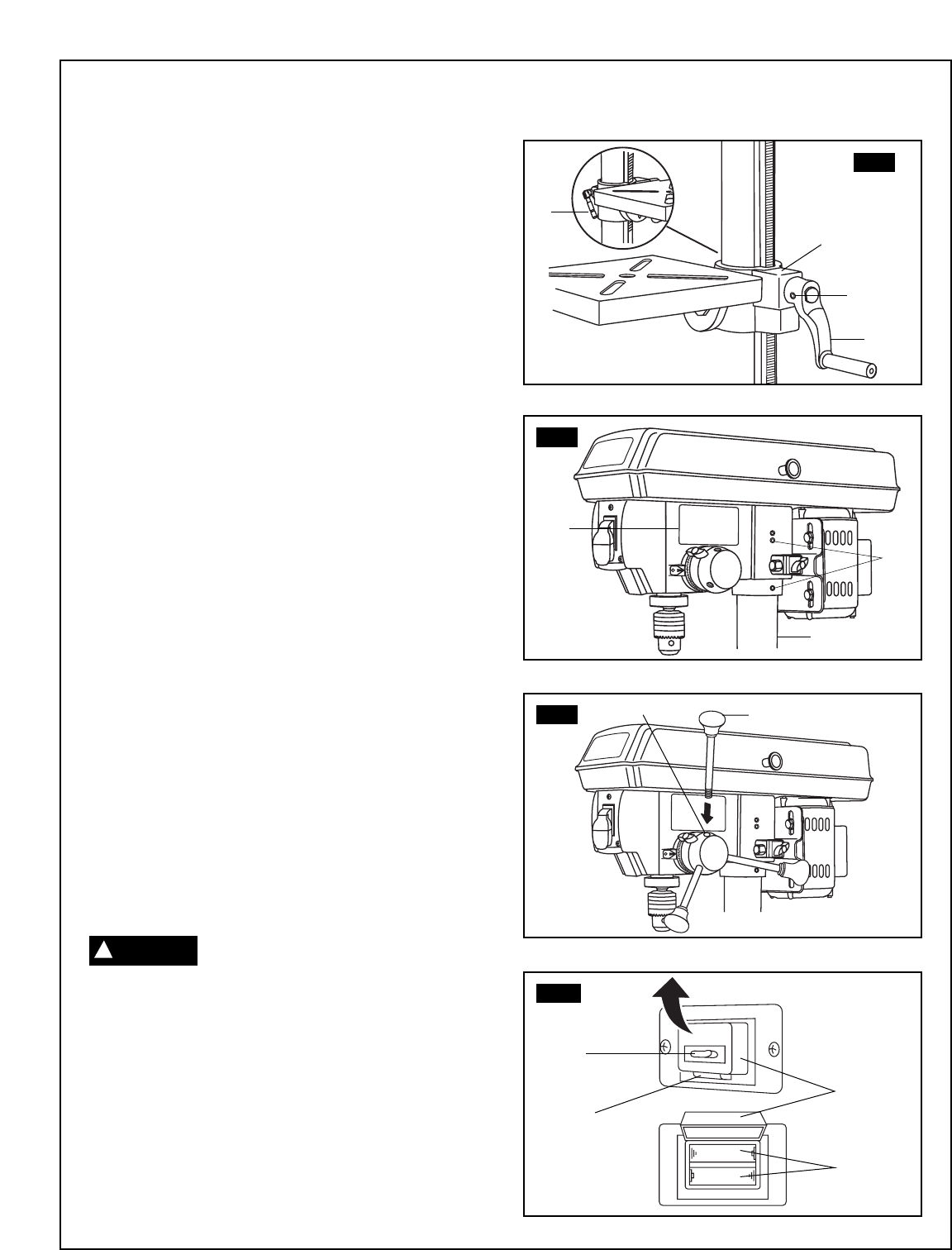
Laser batteries (Fig. 10)
1. Turn off the laser.
2. Press the tab (1) located below the laser switch (2)
and lift up the laser switch cover (3).
3. Insert 2 "AA" batteries in the laser battery
compartment
(4).
4. Close the laser switch cover.
Remove the laser light batteries
when the tool is to be stored
without use for a few days or more. If left in
position, the batteries might leak and damage the
laser light assembly. Damage due to leaking
batteries is not covered under the warranty.
FIG. 7
8
11
FIG. 8
3
1
FIG. 9
1
1
FIG. 10
3
2
9
10
2
2
CAUTION
!
4
1