


10.
Assembly and adjustments
To reduce the risk of injury, never
c
onnect plug to power source outlet
u
ntil all assembly steps are completed.
Tools needed for assembly
• Adjustable wrench
• Phillips
®
screwdriver
• Hammer and block of wood
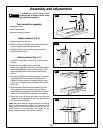
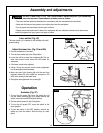
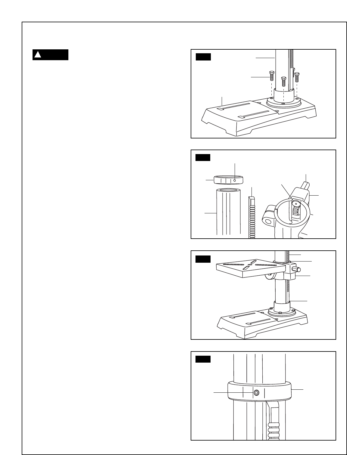
Base to column (Fig. 3)
1. Set the base (1) on the floor.
2. Place the column tube (2) on the base (1), align the
column support holes with the base holes.
3. Install a bolt (3) in each column support hole and
tighten with the wrench.
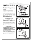
Table to column (Fig. 4–7)
1. Loosen set screw (2) in column ring (1) and remove
the ring.
2. Remove the rack (3) from the column (4).
3. Insert worm shaft (5) into the hole of the table support
crank handle (6) from inside the table support. The
worm shaft (5) should extend outside the housing
about 1”.
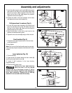
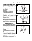
4. Insert the rack (3) into the geared groove of the table
support (6). Make sure the worm shaft (5) on the
inside of the table support is engaged with the teeth
of the rack. The table support should sit at the center
of the rack.
5. Slide the table support and rack assembly (3, 5, 6)
down together onto the column. Insert the bottom
edge of the rack into the lip (7) of the column support.
HOLD IN THIS POSITION until step 6 is completed.
6.
Place the collar
(1) bevel side down over the rack.
Tighten the set screw (2) with the 3 mm Allen wrench
to hold the rack in position.
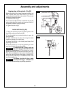
Note: Make sure there is enough clearance to allow the
table to rotate around the column. The collar must sit
loosely over rack and not angled on the column. To
avoid column or collar damage, only tighten the set
screw enough to keep collar in place (Figure 6).
FIG. 3
FIG. 4
FIG. 5
FIG. 6
2
3
1
1
4
2
3
6
5
5
6
7
3
5
2
1
W
ARNING
!